Dodge Dakota (R1). Manual - part 465
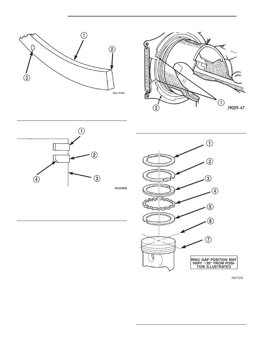
Ring Gap Orientation
• Position the gaps on the piston as shown (Fig.
62).
• Oil spacer - Gap on center line of piston skirt.
• Oil rails - gap 180° apart on centerline of piston
pin bore.
• No. 2 Compression ring - Gap 180° from top oil
rail gap.
• No. 1 Compression ring - Gap 180° from No. 2
compression ring gap.
Fig. 59 Second Compression Ring Identification
1 - SECOND COMPRESSION RING
2 - CHAMFER
3 - ONE DOT
Fig. 60 Compression Ring Chamfer Location
1 - TOP COMPRESSION RING
2 - SECOND COMPRESSION RING
3 - PISTON
4 - CHAMFER
Fig. 61 Compression Ring
1 - COMPRESSION RING
2 - RING EXPANDER RECOMMENDED
Fig. 62 Ring Gap Orientation
1 - TOP COMPRESSION RING
2 - BOTTOM COMPRESSION RING
3 - TOP OIL CONTROL RAIL
4 - OIL RAIL SPACER
5 - BOTTOM OIL CONTROL RAIL
6 - IMAGINARY LINE PARALLEL TO PISTON PIN
7 - IMAGINARY LINE THROUGH CENTER OF PISTON SKIRT
9 - 48
ENGINE 2.5L
AN
PISTON RINGS (Continued)