Dodge Dakota (R1). Manual - part 466


  Index      Dodge     Dodge Dakota (R1) - service repair manual 2000 year


Search            


Content   ..  464  465  466  467   ..


Dodge Dakota (R1). Manual - part 466


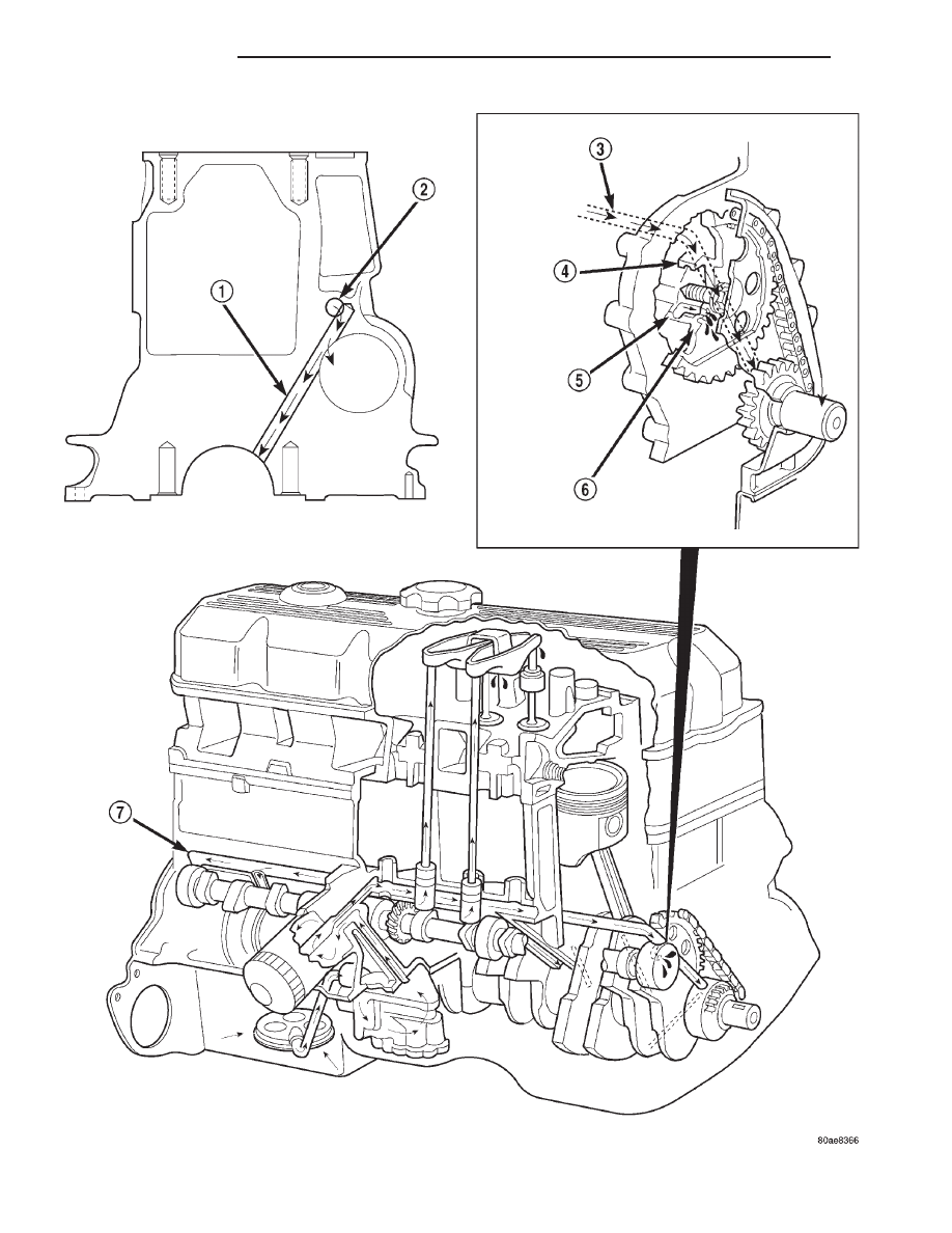
Fig. 67 Oil Lubrication System—2.5L Engine

9 - 52

ENGINE 2.5L

AN

LUBRICATION (Continued)

(9) Gradually apply air pressure from 1 psi to 2.5

psi maximum while applying soapy water at the sus-
pected source. Adjust the regulator to the suitable
test pressure that provide the best bubbles which
will pinpoint the leak source. If the oil leak is
detected and identified, repair per service manual
procedures.

(10) If the leakage occurs at the rear oil seal area,

refer to the section, Inspection for Rear Seal Area
Leak.

(11) If no leaks are detected, turn off the air sup-

ply and remove the air hose and all plugs and caps.
Install the PCV valve and breather cap hose. Proceed
to next step.

(12) Clean the oil off the suspect oil leak area

using a suitable solvent. Drive the vehicle at various
speeds approximately 24 km (15 miles). Inspect the
engine for signs of an oil leak by using a black light.

DIAGNOSIS AND TESTING—ENGINE OIL
PRESSURE

(1) Remove oil pressure sending unit.
(2) Install Oil Pressure Line and Gauge Tool

C-3292. Start engine and record pressure. (Refer to 9
- ENGINE - SPECIFICATIONS).

OIL

STANDARD PROCEDURE - ENGINE OIL

OIL LEVEL INDICATOR (DIPSTICK)

The engine oil level indicator is located at the right

front of the engine, left of the generator (Fig. 68).

CRANKCASE OIL LEVEL INSPECTION

CAUTION: Do not overfill crankcase with engine oil,
oil foaming and oil pressure loss can result.

To ensure proper lubrication of an engine, the

engine oil must be maintained at an acceptable level.
The acceptable levels are indicated between the ADD
and SAFE marks on the engine oil dipstick.

(1) Position vehicle on level surface.
(2) With engine OFF, allow approximately ten min-

utes for oil to settle to bottom of crankcase, remove
engine oil dipstick.

(3) Wipe dipstick clean.
(4) Install dipstick and verify it is seated in the

tube.

(5) Remove dipstick, with handle held above the

tip, take oil level reading.

(6) Add oil only if level is below the ADD mark on

dipstick.

ENGINE OIL CHANGE

Change engine oil at mileage and time intervals

described in the Maintenance Schedule. This infor-
mation can be found in the owner’s manual.

TO CHANGE ENGINE OIL

Run engine until achieving normal operating tem-

perature.

(1) Position the vehicle on a level surface and turn

engine off.

(2) Hoist vehicle.
(3) Remove oil fill cap.
(4) Place a suitable drain pan under crankcase

drain.

(5) Remove drain plug from crankcase and allow

oil to drain into pan. Inspect drain plug threads for
stretching or other damage. Replace drain plug and
gasket if damaged.

(6) Install drain plug in crankcase.
(7) Change oil filter (Refer to 9 - ENGINE/LUBRI-

CATION/OIL FILTER - REMOVAL).

1 - CAM/CRANK MAIN GALLERY (5)
2 - TAPPET GALLERY
3 - TAPPET GALLERY
4 - CAMSHAFT BEARING

5 - NUMBER 1 CAMSHAFT BEARING JOURNAL
6 - CAMSHAFT SPROCKET
7 - TAPPET GALLERY

Fig. 68 Oil Level Indicator Location

1 - CYLINDER HEAD COVER
2 - ENGINE OIL FILL CAP
3 - DIPSTICK
4 - ENGINE OIL FILTER
5 - FILTER BOSS

AN

ENGINE 2.5L

9 - 53

LUBRICATION (Continued)

(8) Lower vehicle and fill crankcase with specified

type (Refer to LUBRICATION & MAINTENANCE/
FLUID TYPES - DESCRIPTION) and amount of
engine oil (Refer to LUBRICATION & MAINTE-
NANCE - SPECIFICATIONS).

(9) Install oil fill cap.
(10) Start engine and inspect for leaks.
(11) Stop engine and inspect oil level.

OIL FILTER

REMOVAL

All engines are equipped with a high quality full-

flow, disposable type oil filter. DaimlerChrysler Cor-
poration recommends a Mopar

t or equivalent oil

filter be used.

(1) Position a drain pan under the oil filter.
(2) Using a suitable oil filter wrench loosen filter.
(3) Rotate the oil filter counterclockwise to remove

it from the cylinder block oil filter boss (Fig. 69).

(4) When filter separates from adapter nipple, tip

gasket end upward to minimize oil spill. Remove fil-
ter from vehicle.

(5) With a wiping cloth, clean the gasket sealing

surface (Fig. 70) of oil and grime.

(6) Install new filter (Refer to 9 - ENGINE/LUBRI-

CATION/OIL FILTER - INSTALLATION).

INSTALLATION

(1) Lightly lubricate oil filter gasket with engine

oil or chassis grease.

(2) Thread filter onto adapter nipple. When gasket

makes contact with sealing surface, (Fig. 70) hand
tighten filter one full turn, do not over tighten.

(3) Add oil (Refer to 9 - ENGINE/LUBRICATION/

OIL - STANDARD PROCEDURE).

OIL PAN

REMOVAL

(1) Disconnect negative cable from battery.
(2) Raise the vehicle.
(3) Remove the oil pan drain plug and drain the

engine oil.

(4) Disconnect the exhaust pipe at the engine

exhaust manifold.

(5) Disconnect the exhaust hanger at the catalytic

converter and lower the pipe.

(6) Remove the engine starter motor.
(7) Remove the flywheel/torque converter housing

access cover.

(8) Position a jack stand directly under the engine

vibration damper.

(9) Place a piece of wood (2 x 2) between the jack

stand and the engine vibration damper.

(10) Remove the engine mount through bolts.
(11) Using the jack stand, raise the engine until

adequate clearance is obtained to remove the oil pan.

(12) If

equipped,

disconnect

the

transmission

cooler lines and oxygen sensor harness from oil pan
mounting studs.

(13) Remove the oil pan bolts and studs. Carefully

remove the oil pan and gasket.

CLEANING

Clean the block and pan gasket surfaces.
Trim or remove excess sealant film in the rear

main cap oil pan gasket groove. DO NOT remove
the sealant inside the rear main cap slots.

If present, trim excess sealant from inside the

engine.

Clean oil pan in solvent and wipe dry with a clean

cloth.

Clean oil screen and pipe thoroughly in clean sol-

vent. Inspect condition of screen.

Fig. 69 Oil Filter Removal—Typical

1 - ENGINE OIL FILTER
2 - OIL FILTER WRENCH

Fig. 70 Oil Filter Sealing Surface—Typical

1 - SEALING SURFACE
2 - RUBBER GASKET
3 - OIL FILTER

9 - 54

ENGINE 2.5L

AN

OIL (Continued)

INSPECTION

Inspect oil drain plug and plug hole for stripped or

damaged threads. Repair as necessary.

Inspect oil pan mounting flange for bends or distor-

tion. Straighten flange, if necessary.

INSTALLATION

(1) Clean the block and pan gasket surfaces.
(2) Fabricate 4 alignment dowels from 1/4 x 1 1/2

inch bolts. Cut the head off the bolts and cut a slot
into the top of the dowel. This will allow easier
installation and removal with a screwdriver (Fig. 71).

(3) Install two dowels in the timing case cover.

Install the other two dowels in the cylinder block
(Fig. 72).

(4) Apply Mopar

t Silicone Adhesive Sealant onto

the cylinder block in four location as shown (Fig. 73)

(5) Slide the one-piece gasket over the dowels and

onto the block and timing case cover.

(6) Position the oil pan over the dowels and onto

the gasket.

(7) Install the 1/4 inch oil pan bolts. Tighten these

bolts to 9.5 N·m (84 in. lbs.) torque. Install the 5/16
inch oil pan bolts (Fig. 74). Tighten these bolts to 15
N·m (132 in. lbs.) torque.

(8) Remove the dowels. Install the remaining 1/4

inch oil pan bolts. Tighten these bolts to 9.5 N·m (84
in. lbs.) torque.

(9) Lower the engine until it is properly located on

the engine mounts.

(10) Install the through bolts and tighten the nuts.
(11) Lower the jack stand and remove the piece of

wood.

Fig. 71 Fabrication of Alignment Dowels

1 - 1/4'' × 1 1/2'' BOLT
2 - DOWEL
3 - SLOT

Fig. 72 Position of Dowels in Cylinder Block

1 - 5/16'' HOLES
2 - DOWEL HOLES
3 - CYLINDER BLOCK
4 - 5/16'' HOLES

Fig. 73 Location of Mopar

T

Silicone Adhesive

Sealant on

1 - SEALER LOCATIONS

Fig. 74 Position of 5/16 inch Oil Pan Bolts

1 - OIL PAN
2 - OIL PAN DRAIN PLUG

AN

ENGINE 2.5L

9 - 55

OIL PAN (Continued)


Content   ..  464  465  466  467   ..