Dodge Dakota (R1). Manual - part 464


  Index      Dodge     Dodge Dakota (R1) - service repair manual 2000 year


Search            


Content   ..  462  463  464  465   ..


Dodge Dakota (R1). Manual - part 464


STANDARD PROCEDURE—PISTON FITTING

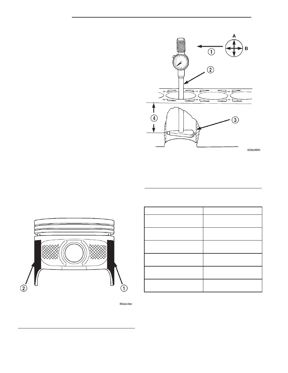
(1) To correctly select the proper size piston, a cyl-

inder bore gauge, capable of reading in 0.003 mm (
.0001 in.) INCREMENTS is required. If a bore gauge
is not available, do not use an inside micrometer.

(2) Measure the inside diameter of the cylinder

bore at a point 49.5 mm (1-15/16 inches) below top of
bore. Start perpendicular (across or at 90 degrees) to
the axis of the crankshaft at point A and then take
an additional bore reading 90 degrees to that at point
B (Fig. 51).

(3) The coated pistons will be serviced with the

piston pin and connecting rod pre-assembled. The
coated piston connecting rod assembly can be
used to service previous built engines and
MUST be replaced as complete sets. 
Tin coated
pistons should not be used as replacements for coated
pistons.

(4) The coating material is applied to the piston

after the final piston machining process. Measuring
the outside diameter of a coated piston will not pro-
vide accurate results (Fig. 50). Therefore measuring
the inside diameter of the cylinder bore with a dial
Bore Gauge is MANDATORY. To correctly select the
proper size piston, a cylinder bore gauge capable of
reading in 0.003 mm (.0001 in.) increments is
required.

(5) Piston

installation

into

the

cylinder

bore

requires slightly more pressure than that required
for non-coated pistons. The bonded coating on the
piston will give the appearance of a line-to-line fit
with the cylinder bore.

PISTON SIZE CHART

CYLINDER BORE SIZE

PISTON LETTER SIZE

98.438 - 98.448 mm

(3.8755 - 3.8759 in.)

A

98.448 - 98.458 mm

(3.8759 - 3.8763 in.)

B

98.458 - 98.468 mm

(3.8763 - 3.8767 in.)

C

98.468 - 98.478 mm

(3.8767 - 3.8771 in.)

D

98.478 - 98.488 mm

(3.8771 - 3.8775 in.)

E

98.488 - 98.498 mm

(3.8775 - 3.8779 in.)

F

REMOVAL

(1) Remove the engine cylinder head cover (Refer

to

9

-

ENGINE/CYLINDER

HEAD/CYLINDER

HEAD COVER(S) - REMOVAL).

(2) Remove the rocker arms, bridges and pivots.
(3) Remove the push rods.
(4) Remove the engine cylinder head (Refer to 9 -

ENGINE/CYLINDER HEAD - REMOVAL).

Fig. 50 Moly Coated Piston

1 - MOLY COATED
2 - MOLY COATED

Fig. 51 Bore Gauge

1 - FRONT
2 - BORE GAUGE
3 - CYLINDER BORE
4 - 38 MM
(1.5 in)

9 - 44

ENGINE 2.5L

AN

PISTON & CONNECTING ROD (Continued)

(5) Position the pistons one at a time near the bot-

tom of the stroke. Use a ridge reamer to remove the
ridge from the top end of the cylinder walls. Use a
protective cloth to collect the cuttings.

(6) Raise the vehicle.
(7) Drain the engine oil.
(8) Remove the oil pan (Refer to 9 - ENGINE/LU-

BRICATION/OIL PAN - REMOVAL) and gasket.

(9) Remove the connecting rod bearing caps and

inserts. Mark the caps and rods with the cylinder
bore location. The connecting rods and caps are
stamped with a two letter combination (Fig. 52).

(10) Lower the vehicle until it is about 2 feet from

the floor.

CAUTION: Ensure that the connecting rod bolts DO
NOT scratch the crankshaft journals or cylinder
walls. Short pieces of rubber hose, slipped over the
rod bolts will provide protection during removal.

(11) Have an assistant push the piston and con-

necting rod assemblies up and through the top of the
cylinder bores (Fig. 53).

CLEANING

Clean the piston and connecting rod assembly

using a suitable solvent.

INSPECTION

Check the connecting rod journal for excessive

wear, taper and scoring. Refer to Connecting Rod
Bearings in the Service Procedures portion of this
Section.

Check the connecting rod for signs of twist or bend-

ing.

Check the piston for taper and elliptical shape

before it is fitted into the cylinder bore. Refer to Fit-
ting Pistons in the Service Procedures portion of this
Section.

Check the piston for scoring, or scraping marks in

the piston skirts. Check the ring lands for cracks
and/or deterioration.

INSTALLATION

(1) Clean the cylinder bores thoroughly. Apply a

light film of clean engine oil to the bores with a clean
lint-free cloth.

(2) Install the piston rings on the pistons if

removed (Refer to 9 - ENGINE/ENGINE BLOCK/
PISTON RINGS - STANDARD PROCEDURE).

(3) Lubricate the piston and rings with clean

engine oil.

CAUTION: Ensure that connecting rod bolts do not
scratch the crankshaft journals or cylinder walls.
Short pieces of rubber hose slipped over the con-
necting rod bolts will provide protection during
installation.

Fig. 52 Stamped Connecting Rods and Caps

1 - CONNECTING ROD CAP
2 - CONNECTING ROD

Fig. 53 Removal of Connecting Rod and Piston

Assembly

1 - PISTON
2 - CONNECTING ROD
3 - CYLINDER BLOCK

AN

ENGINE 2.5L

9 - 45

PISTON & CONNECTING ROD (Continued)

(4) Use a piston ring compressor to install the con-

necting rod and piston assemblies through the top of
the cylinder bores (Fig. 54).

(5) Ensure the arrow on the piston top points to

the front of the engine (Fig. 54).

(6) Raise the vehicle.
(7) Each bearing insert is fitted to its respective

journal to obtain the specified clearance between the
bearing and the journal. In production, the select fit
is obtained by using various-sized, color-coded bear-
ing inserts as listed in the Connecting Rod Bearing
Fitting

Chart

(Refer

to

9

-

ENGINE/ENGINE

BLOCK/CONNECTING ROD BEARINGS - STAN-
DARD PROCEDURE). The color code appears on the
edge of the bearing insert. The size is not stamped on
inserts used for production of engines.

(8) The rod journal is identified during the engine

production by a color-coded paint mark on the adja-
cent cheek or counterweight toward the flange (rear)
end of the crankshaft. The color codes used to indi-
cate journal sizes are listed in the Connecting Rod
Bearing Fitting Chart.

(9) When

required,

upper

and

lower

bearing

inserts of different sizes may be used as a pair refer
to Connecting Rod Bearing Fitting Chart (Refer to 9 -
ENGINE/ENGINE

BLOCK/CONNECTING

ROD

BEARINGS - STANDARD PROCEDURE). A stan-
dard size insert is sometimes used in combination
with a 0.025 mm (0.001 inch) undersize insert to
reduce clearance 0.013 mm (0.0005 inch).

CAUTION: DO NOT intermix bearing caps. Each
connecting rod and bearing cap are stamped with
the cylinder number. The stamp is located on a
machined surface adjacent to the oil squirt hole
that faces the camshaft side of the cylinder block.

(10) Install the connecting rod bearing caps and

inserts in the same positions as removed.

CAUTION: Verify that the oil squirt holes in the rods
face the camshaft and that the arrows on the pis-
tons face the front of the engine.

(11) Install the oil pan (Refer to 9 - ENGINE/LU-

BRICATION/OIL PAN - INSTALLATION) and gas-
ket.

(12) Lower the vehicle.
(13) Install the engine cylinder head (Refer to 9 -

ENGINE/CYLINDER

HEAD

-

INSTALLATION),

push rods, rocker arms, bridges, pivots and engine
cylinder head cover (Refer to 9 - ENGINE/CYLIN-
DER

HEAD/CYLINDER

HEAD

COVER(S)

-

INSTALLATION).

(14) Fill the crankcase with engine oil.

PISTON RINGS

STANDARD PROCEDURE - PISTON RING
FITTING

(1) Carefully

clean

the

carbon

from

all

ring

grooves. Oil drain openings in the oil ring groove and
pin boss must be clear. DO NOT remove metal from
the grooves or lands. This will change ring-to-groove
clearances and will damage the ring-to-land seating.

(2) Be sure the piston ring grooves are free of

nicks and burrs.

(3) Measure the ring side clearance with a feeler

gauge fitted snugly between the ring land and ring
(Fig. 55) (Fig. 56). Rotate the ring in the groove. It
must move freely around circumference of the groove.

Fig. 54 Rod and Piston Assembly Installation

Fig. 55 Piston Dimensions

9 - 46

ENGINE 2.5L

AN

PISTON & CONNECTING ROD (Continued)

RING SIDE CLEARANCE CHART

ITEM

SPECIFICATION

Top Compression Ring

0.042 - 0.084 mm

(0.0017 - 0.0033 in.)

Second Compression

Ring

0.042 - 0.084 mm

(0.0017 - 0.0033 in.)

Oil Control Ring

0.06 - 0.21 mm

(0.0024 - 0.0083 in.)

(4) Place ring in the cylinder bore and push down

with inverted piston to position near lower end of the
ring travel. Measure ring gap with a feeler gauge fit-
ting snugly between ring ends (Fig. 57).

RING GAP MEASUREMENT CHART

ITEM

SPECIFICATION

Top Compression Ring

0.229 - 0.610 mm

(0.0090 - 0.0240 in.)

Second Compression

Ring

0.483 - 0.965 mm

(0.0190 - 0.080 in.)

Oil Control Ring

0.254 - 1.500 mm

(0.010 - 0.060 in.)

(5) The oil control rings are symmetrical, and can

be installed with either side up. It is not necessary to
use a tool to install the upper and lower rails. Insert
oil rail spacer first, then side rails.

(6) The two compression rings are different and

cannot be interchanged. The top compression ring
can be identified by the shiny coating on the outer
sealing surface and can be installed with either side
up. (Fig. 58).

(7) The second compression ring has a slight

chamfer on the bottom of the inside edge and a dot
on the top for correct installation (Fig. 60).

(8) Using a ring installer, install the second com-

pression ring with the dot facing up (Fig. 59) (Fig.
61).

(9) Using a ring installer, install the top compres-

sion ring (either side up).

Fig. 56 Ring Side Clearance Measurement

1 - FEELER GAUGE

Fig. 57 Gap Measurement

1 - FEELER GAUGE

Fig. 58 Top Compression ring

1 - TOP COMPRESSION RING

AN

ENGINE 2.5L

9 - 47

PISTON RINGS (Continued)


Content   ..  462  463  464  465   ..