Dodge Dakota (R1). Manual - part 459


  Index      Dodge     Dodge Dakota (R1) - service repair manual 2000 year


Search            


Content   ..  457  458  459  460   ..


Dodge Dakota (R1). Manual - part 459


(18) Attach the air conditioning compressor mount-

ing bracket to the engine cylinder head and block.
Tighten the bolts to 40 N·m (30 ft. lbs.) torque.

(19) Attach the air conditioning compressor to the

bracket. Tighten the bolts to 27 N·m (20 ft. lbs.)
torque.

CAUTION: The accessory drive belt must be routed
correctly. Incorrect routing can cause the water
pump to turn in the opposite direction causing the
engine to overheat.

(20) Install the accessory drive belt and correctly

tension the belt (Refer to 7 - COOLING/ACCESSORY
DRIVE/DRIVE BELTS - INSTALLATION).

(21) Install the resonator assembly and air in-let

hose. Tighten clamps to 4 N·m (35 in. lbs.).

(22) Connect the hoses to the thermostat housing.
(23) Install the coolant temperature sending unit

connector.

(24) Connect negative cable to battery.
(25) Connect the upper radiator hose and heater

hose at the thermostat housing.

(26) Fill the cooling system. (Refer to 7 - COOL-

ING - STANDARD PROCEDURE) Check for leaks.

WARNING: USE EXTREME CAUTION WHEN THE
ENGINE IS OPERATING. DO NOT STAND IN DIRECT
LINE WITH THE FAN. DO NOT PUT HANDS NEAR
THE PULLEYS, BELTS OR FAN. DO NOT WEAR
LOOSE CLOTHING.

(27) Operate the engine with the radiator cap off.

Inspect for leaks and continue operating the engine
until the thermostat opens. Add coolant, if required.

CYLINDER HEAD COVER(S)

REMOVAL

A cured gasket is part of the engine cylinder head

cover.

(1) Disconnect negative cable from battery.
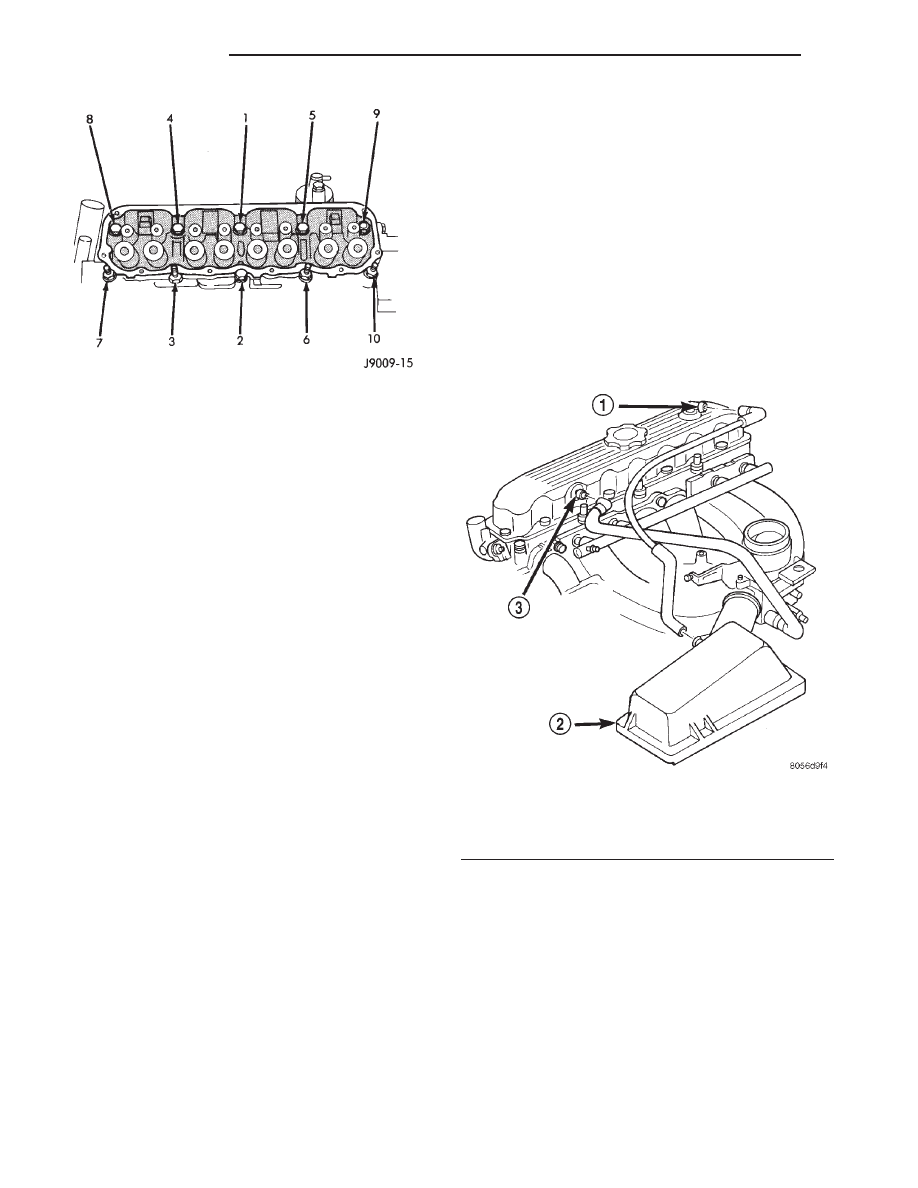
(2) Disconnect the Crankcase Ventilation (CCV)

vacuum hose from engine cylinder head cover (Fig.
17).

(3) Remove the air inlet hose and resonator from

the air cleaner and throttle body.

(4) Remove the engine cylinder head cover mount-

ing bolts.

(5) Remove the engine cylinder head cover (Fig.

17).

(6) Remove any original sealer from the cover seal-

ing surface of the engine cylinder head and clean the
surface using a fabric cleaner.

(7) Remove all residue from the sealing surface

using a clean, dry cloth.

CLEANING

Clean cylinder head cover gasket surface.
Clean head rail, if necessary.

INSPECTION

Inspect cover for distortion and straighten, if nec-

essary.

Fig. 16 Engine cylinder head Bolt Tightening

Sequence

Fig. 17 Engine Cylinder Head Cover

1 - AIR INLET FITTING
2 - AIR FILTER COVER
3 - FIXED ORIFICE FITTING

9 - 24

ENGINE 2.5L

AN

CYLINDER HEAD (Continued)

Check the gasket for use in head cover installation.

If damaged, use a new gasket.

INSTALLATION

A cured gasket is part of the engine cylinder head

cover.

(1) Inspect the engine cylinder head cover for

cracks. Replace the cover, if cracked.

NOTE: The original dark grey gasket material
should NOT be removed. If sections of the gasket
material are missing or are compressed, replace the
engine cylinder head cover. However, sections with
minor damage such as small cracks, cuts or chips
may be repaired with a hand held applicator. The
new material must be smoothed over to maintain
gasket height. Allow the gasket material to cure
prior to engine cylinder head cover installation.

(2) If a replacement cover is installed, transfer the

CCV valve grommet the oil filler cap from the origi-
nal cover to the replacement cover.

(3) Install engine cylinder head cover. Tighten the

mounting bolts to 13 N·m (115 in. lbs.) torque.

(4) Connect the CCV hoses (Fig. 17).
(5) Connect negative cable to battery.
(6) Install the air inlet hose and resonator.

ROCKER ARMS

REMOVAL

(1) Remove the engine cylinder head cover (Refer

to

9

-

ENGINE/CYLINDER

HEAD/CYLINDER

HEAD COVER(S) - REMOVAL).

(2) Check for rocker arm bridges which are caus-

ing misalignment of the rocker arm to valve tip area.

(3) Remove the capscrews at each bridge and pivot

assembly (Fig. 18). Alternately loosen the capscrews
one turn at a time to avoid damaging the bridges.

(4) Remove the bridges, pivots and corresponding

pairs of rocker arms (Fig. 18). Place them on a bench
in the same order as removed.

(5) Remove the push rods and place them on a

bench in the same order as removed.

(6) Clean all the components with cleaning sol-

vent.

(7) Use compressed air to blow out the oil passages

in the rocker arms and push rods.

CLEANING

Clean all the components with cleaning solvent.
Use compressed air to blow out the oil passages in

the rocker arms and push rods.

INSPECTION

Inspect the pivot surface area of each rocker arm.

Replace any that are scuffed, pitted, cracked or
excessively worn.

Inspect the valve stem tip contact surface of each

rocker arm and replace any rocker arm that is deeply
pitted.

Inspect each push rod end for excessive wear and

replace as required. If any push rod is excessively
worn because of lack of oil, replace it and inspect the
corresponding hydraulic tappet for excessive wear.

Inspect the push rods for straightness by rolling

them on a flat surface or by shining a light between
the push rod and the flat surface.

A wear pattern along the length of the push rod is

not normal. Inspect the engine cylinder head for
obstruction if this condition exists.

INSTALLATION

(1) Lubricate the ball ends of the push rods with

Mopar

t Engine Oil Supplement, or equivalent and

install push rods in their original locations. Ensure
that the bottom end of each push rod is centered in
the tappet plunger cap seat.

(2) Using Mopar

t Engine Oil Supplement, or

equivalent, lubricate the area of the rocker arm that

Fig. 18 Rocker Arm Assembly

1 - CAPSCREWS
2 - BRIDGE
3 - PIVOT ASSEMBLY
4 - PUSH RODS
5 - ROCKER ARMS

AN

ENGINE 2.5L

9 - 25

CYLINDER HEAD COVER(S) (Continued)

the pivot contacts. Install rocker arms, pivots and
bridge above each cylinder in their original position.

(3) Loosely install the capscrews through each

bridge.

(4) At each bridge, tighten the capscrews alter-

nately, one turn at a time, to avoid damaging the
bridge. Tighten the capscrews to 28 N·m (21 ft. lbs.)
torque.

(5) Install the engine cylinder head cover (Refer to

9 - ENGINE/CYLINDER HEAD/CYLINDER HEAD
COVER(S) - INSTALLATION).

INTAKE/EXHAUST VALVES &
SEATS

DESCRIPTION

Both the intake and exhaust valves are made of

steel. The intake valve is 48.768 mm (1.92 inches) in
diameter and the exhaust valve is 41.148 mm (1.62
inches) in diameter and has a 2.032 mm (0.080 inch)
wafer interia welded to the tip for durability. These
valves are not splayed.

STANDARD PROCEDURE—VALVE TIMING
VERIFICATION

• Disconnect the spark plug wires and remove the

spark plugs.

• Remove the engine cylinder head cover.

• Remove the capscrews, bridge and pivot assem-

bly, and rocker arms from above the No.1 cylinder.

• Alternately loosen each capscrew, one turn at a

time, to avoid damaging the bridge.

• Rotate the crankshaft until the No.4 piston is at

top dead center (TDC) on the compression stroke.

• Rotate the crankshaft counterclockwise (viewed

from the front of the engine) 90°.

• Install a dial indicator on the end of the No.1

cylinder intake valve push rod. Use rubber tubing to
secure the indicator stem on the push rod.

• Set the dial indicator pointer at zero.

• Set the dial indicator pointer at zero.

• Rotate the crankshaft clockwise (viewed from

the front of the engine) until the dial indicator
pointer indicates 0.305 mm (0.012 inch) travel dis-
tance (lift).

• The timing notch index on the vibration damper

should be aligned with the TDC mark on the timing
degree scale.

• If the timing notch is more than 13 mm (1/2

inch) away from the TDC mark in either direction,
the valve timing is incorrect.

• If the valve timing is incorrect, the cause may be

a broken camshaft pin. It is not necessary to replace
the camshaft because of pin failure. A spring pin is
available for service replacement.

STANDARD PROCEDURE—REFACING VALVES
AND SEATS

VALVE REFACING

The intake and exhaust valves have a 43-1/4° to

43-3/4° face angle and a 44-1/4° to 44-3/4° seat angle
(Fig. 19).

VALVE FACE AND VALVE SEAT ANGLE CHART

ITEM

DESCRIPTION

SPECIFICATION

A

SEAT WIDTH

INTAKE

1.016 - 1.524 mm

(0.040 - 0.060 in.)

EXHAUST

1.524 - 2.032 mm

(0.060 - 0.080 in.)

B

FACE ANGLE

(INT. AND EXT.)

43¼° - 43¾°

C

SEAT ANGLE

(INT. AND EXT.)

44¼° - 44¾°

D

CONTACT

SURFACE

Inspect the remaining margin after the valves are

refaced (Fig. 20). Valves with less than 1.190 mm
(0.047 in.) margin should be discarded.

Fig. 19 Valve Face and

1 - CONTACT POINT
A,B,C and D Refer to VALVE FACE AND VALVE SEAT ANGLE
CHART

9 - 26

ENGINE 2.5L

AN

ROCKER ARMS (Continued)

VALVE SEAT REFACING

CAUTION: DO NOT un-shroud valves during valve
seat refacing (Fig. 21).

(1) When refacing valve seats, it is important that

the correct size valve guide pilot be used for reseat-
ing stones. A true and complete surface must be
obtained.

(2) Measure the concentricity of valve seat using a

dial indicator. Total runout should not exceed 0.051
mm (0.002 in.) total indicator reading.

(3) Inspect the valve seat with Prussian blue, to

determine where the valve contacts the seat. To do
this, coat valve seat LIGHTLY with Prussian blue
then set valve in place. Rotate the valve with light
pressure. If the blue is transferred to the center of
valve face, contact is satisfactory. If the blue is trans-
ferred to the top edge of valve face, lower valve seat
with a 15° stone. If the blue is transferred to bottom
edge of valve face raise valve seat with a 60° stone.

(4) When seat is properly positioned the width of

intake seats should be 1.016-1.524 mm (0.040-0.060
in.). The width of the exhaust seats should be 1.524-
2.032 mm (0.060-0.080 in.).

REMOVAL—VALVES

NOTE: This procedure is done with the head
removed.

(1) Compress valve springs using Valve Spring

Compressor Tool MD-998772-A and adapter 6716A.

(2) Remove valve retaining locks, valve spring

retainers, valve stem seals, and valve springs.

(3) Before removing valves, remove any burrs from

valve stem lock grooves to prevent damage to the
valve guides. Identify valves to ensure installation in
original locations.

CLEANING

Clean valves thoroughly. Discard burned, warped,

or cracked valves.

Remove carbon and varnish deposits from inside of

valve guides with a reliable guide cleaner.

INSTALLATION—VALVES

(1) Coat valve stems with lubrication oil and insert

them in cylinder head.

(2) If valves or seats are reground, check valve stem

height. If valve is too long, replace cylinder head.

(3) Install new seals on all valve guides. Install

valve springs and valve retainers.

(4) Compress valve springs with Valve Spring

Compressor Tool MD-998772A and adapter 6716A,
install locks and release tool. If valves and/or seats
are ground, measure the installed height of springs.
Be sure the measurement is taken from bottom of
spring seat in cylinder head to the bottom surface of
spring retainer. If spacers are installed, measure
from the top of spacer. If height is greater than 42.86
mm (1-11/16 inches), install a 1.587 mm (1/16 in.)
spacer in head counterbore. This should bring spring
height back to normal 41.27 to 42.86 mm (1-5/8 to
1-11/16 in.).

Fig. 20 Intake and Exhaust Valves

1 - MARGIN
2 - VALVE SPRING RETAINER LOCK GROOVE
3 - STEM
4 - FACE

Fig. 21 Refacing Valve Seats

1 - STONE
2 - PILOT
3 - VALVE SEAT
4 - SHROUD

AN

ENGINE 2.5L

9 - 27

INTAKE/EXHAUST VALVES & SEATS (Continued)


Content   ..  457  458  459  460   ..