Dodge Dakota (R1). Manual - part 457
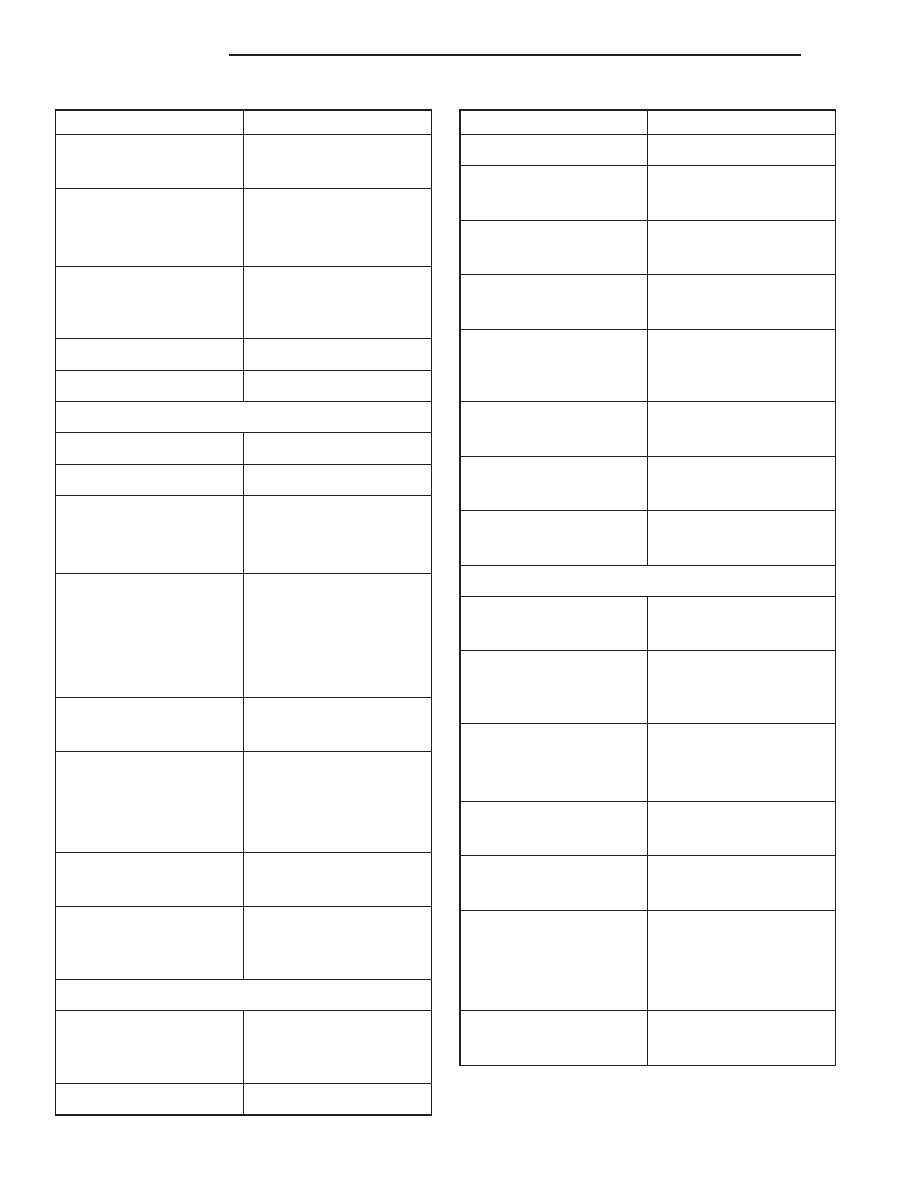
DESCRIPTION
SPECIFICATION
(Preferred)
0.051 mm
(0.002 in.)
Connecting Rod Journal
Diameter
53.17 to 53.23 mm
(2.0934 to 2.0955 in.)
Connecting Rod Journal
Width
27.18 to 27.33 mm
(1.070 to 1.076 in.)
Out of Round - Max
0.013 mm (0.0005 in.)
Taper - Max
0.013 mm (0.0005 in.)
CYLINDER BLOCK
Deck Height
236.73 mm (9.320 in.)
Deck Clearance
0.000 mm (0.000 in.)
Cylinder Bore Diameter—
Standard
98.45 to 98.48 mm
(3.8759 to 3.8775 in.)
Cylinder Bore Diameter—
Taper (Max)
0.025 mm
(0.001 in.)
Out of Round (Max)
0.025 mm
(0.001 in.)
Tappet Bore Diameter
23.000 to 23.025 mm
(0.9055 to 0.9065 in.)
Flatness
0.03 mm per 25 mm
(0.001 in. per 1 in.)
0.05 mm per 152 mm
(0.002 in. per 6 in.)
Flatness Max
0.20 mm for total length
(0.008 in. for total length)
Main Bearing Bore
Diameter
68.3514 to 68.3768 mm
(2.691 to 2.692 in.)
CONNECTING RODS
Total Weight (Less
Bearing)
663 to 671 grams
(23.39 to 23.67 oz.)
Length (Center to Center)
155.52 to 155.62 mm
DESCRIPTION
SPECIFICATION
(6.123 to 6.127 in.)
Piston Pin Bore Diameter
23.59 to 23.62 mm
(0.9288 to 0.9298 in.)
Bore (Less Bearings)
56.08 to 56.09 mm
(2.2080 to 2.2085 in.)
Bearing Clearance
0.025 to 0.076 mm
(0.001 to 0.003 in.)
Bearing Clearance
(Preferred)
0.044 to 0.050 mm
(0.0015 to 0.0020 in.)
Side Clearance
0.25 to 0.48 mm
(0.010 to 0.019 in.)
Twist (Max)
0.002 mm per mm
(0.002 in. per in.)
Bend (Max)
0.006 mm per mm
(0.006 in. per inch.)
CYLINDER HEAD
Combustion Chamber
49.9 to 52.9 cc
(3.04 to 3.23 cu. in.)
Valve Guide I.D.
(Integral)
7.95 to 7.97 mm
(0.313 to 0.314 in.)
Valve Seat Angle
Intake
44.5°
Exhaust
44.5°
Valve Seat Width
1.01 to 1.52 mm
(0.040 to 0.060 in.)
Valve Seat Runout
0.064 mm
(0.0025 in.)
Flatness
0.03 mm per 25 mm
(0.001 in. per 1 in.)
0.05 mm per 152 mm
(0.002 in. per 6 in.)
Flatness (Max)
0.20 mm for total length
(0.008 in. for total length)
9 - 16
ENGINE 2.5L
AN
ENGINE 2.5L (Continued)