Dodge Dakota (R1). Manual - part 458


  Index      Dodge     Dodge Dakota (R1) - service repair manual 2000 year


Search            


Content   ..  456  457  458  459   ..


Dodge Dakota (R1). Manual - part 458


INSTALLATION

(1) Install element into housing.
(2) Position housing cover into housing locating

tabs.

(3) Pry up spring clips and lock cover to housing.

CYLINDER HEAD

DESCRIPTION

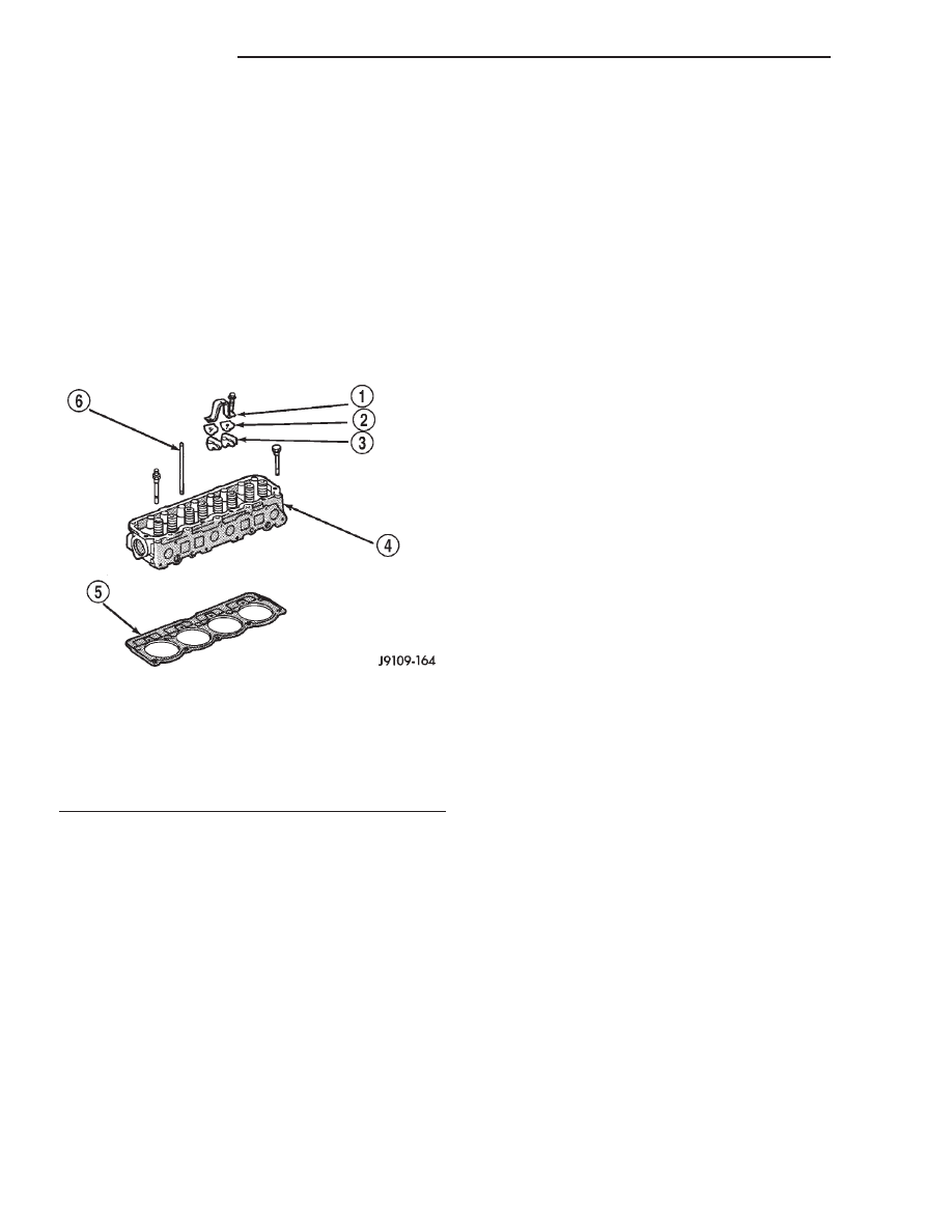
The cast iron cylinder head (Fig. 9) is mounted to

the cylinder block using ten bolts. The spark plugs
are located in the peak of the wedge between the
valves.

OPERATION

The cylinder head closes the combustion chamber

allowing the pistons to compress the air fuel mixture
to the correct ratio for ignition. The valves located in
the cylinder head open and close to either allow clean
air into the combustion chamber or to allow the
exhaust gases out, depending on the stroke of the
engine.

DIAGNOSIS AND TESTING—CYLINDER HEAD
GASKET

A cylinder head gasket leak can be located between

adjacent cylinders or between a cylinder and the
adjacent water jacket.

Possible indications of the cylinder head gasket

leaking between adjacent cylinders are:

• Loss of engine power

• Engine misfiring

• Poor fuel economy
Possible indications of the cylinder head gasket

leaking between a cylinder and an adjacent water
jacket are:

• Engine overheating

• Loss of coolant

• Excessive steam (white smoke) emitting from

exhaust

• Coolant foaming

CYLINDER-TO-CYLINDER LEAKAGE TEST

To determine if an engine cylinder head gasket is

leaking between adjacent cylinders, follow the proce-
dures in Cylinder Compression Pressure Test (Refer
to 9 - ENGINE - DIAGNOSIS AND TESTING). An
engine cylinder head gasket leaking between adja-
cent cylinders will result in approximately a 50–70%
reduction in compression pressure.

CYLINDER-TO-WATER JACKET LEAKAGE TEST

WARNING: USE EXTREME CAUTION WHEN THE
ENGINE IS OPERATING WITH COOLANT PRES-
SURE CAP REMOVED.

VISUAL TEST METHOD

With the engine cool, remove the coolant pressure

cap. Start the engine and allow it to warm up until
thermostat opens.

If a large combustion/compression pressure leak

exists, bubbles will be visible in the coolant.

COOLING SYSTEM TESTER METHOD

WARNING: WITH COOLING SYSTEM TESTER IN
PLACE, PRESSURE WILL BUILD UP FAST. EXCES-
SIVE

PRESSURE

BUILT

UP,

BY

CONTINUOUS

ENGINE OPERATION, MUST BE RELEASED TO A
SAFE PRESSURE POINT. NEVER PERMIT PRES-
SURE TO EXCEED 158 kPa (23 psi).

Install Cooling System Tester 7700 or equivalent to

pressure cap neck. Start the engine and observe the
tester’s pressure gauge. If gauge pulsates with every
power stroke of a cylinder a combustion pressure
leak is evident.

CHEMICAL TEST METHOD

Combustion leaks into the cooling system can also

be checked by using Bloc-Chek Kit C-3685-A or
equivalent. Perform test following the procedures
supplied with the tool kit.

Fig. 9 Cylinder Head—2.5L Engine

1 - BRIDGE
2 - PIVOT ASM.
3 - ROCKER ARM
4 - CYLINDER HEAD
5 - HEAD GASKET
6 - PUSH ROD

9 - 20

ENGINE 2.5L

AN

AIR CLEANER ELEMENT (Continued)

STANDARD PROCEDURE—VALVE GUIDE
WEAR - MEASURING

Measure valve stems for wear. If wear exceeds

0.051 mm (0.002 in.), replace the valve.

Measure valve stem guide clearance as follows:
(1) Install Valve Guide Sleeve Tool C-3973 over

valve stem and install valve (Fig. 10). The special
sleeve places the valve at the correct height for
checking with a dial indicator.

(2) Attach dial indicator Tool C-3339 to cylinder

head and set it at right angles to valve stem being
measured (Fig. 11).

(3) Move valve to and from the indicator. The total

dial indicator reading should not exceed 0.432 mm
(0.017 in.). Ream the guides for valves with oversize
stems if dial indicator reading is excessive or if the
stems are scuffed or scored.

STANDARD PROCEDURE—VALVE GUIDE
SERVICE

Service valves with oversize stems are available.

Refer to REAMER SIZES CHART .

REAMER SIZES CHART

REAMER O/S

VALVE GUIDE SIZE

0.076 mm

8.026 - 8.052 mm

(0.003 in.)

(0.316 - 0.317 in.)

0.381 mm

8.331 - 8.357 mm

(0.015 in.)

(0.328 - 0.329 in.)

(1) Slowly turn reamer by hand and clean guide

thoroughly before installing new valve. Ream the
valve guides from standard to 0.381 mm (0.015
in.). Use a two step procedure so the valve
guides are reamed true in relation to the valve
seat:

• Step 1—Ream to 0.0763 mm (0.003 inch).

• Step 2—Ream to 0.381 mm (0.015 inch).

REMOVAL

This procedure can be done with the engine in or

out of the vehicle.

(1) Disconnect negative cable from battery.

WARNING:

DO

NOT

REMOVE

THE

CYLINDER

BLOCK DRAIN PLUGS OR LOOSEN THE RADIATOR
DRAIN COCK WITH THE SYSTEM HOT AND PRES-
SURIZED BECAUSE SERIOUS BURNS FROM THE
COOLANT CAN OCCUR.

(2) Drain the coolant (Refer to 7 - COOLING -

STANDARD PROCEDURE) and disconnect the hoses
at the engine thermostat housing. DO NOT waste
reusable coolant. If the solution is clean and is being
drained only to service the engine or cooling system,
drain the coolant into a clean container for reuse.

(3) Remove the air in-let hose and resonator

assembly.

(4) Remove the engine cylinder head cover (Refer

to

9

-

ENGINE/CYLINDER

HEAD/CYLINDER

HEAD COVER(S) - REMOVAL).

(5) Remove the capscrews, bridge and pivot assem-

blies and rocker arms (Fig. 12).

(6) Remove the push rods (Fig. 12). Retain the

push rods, bridges, pivots and rocker arms in
the same order as removed.

(7) Loosen the accessory drive belt at the power

steering pump bracket, if equipped or at the idler
pulley bracket (Refer to 7 - COOLING/ACCESSORY
DRIVE/DRIVE BELTS - REMOVAL).

Fig. 10 Positioning Valve with Tool C-3973

1 - VALVE
2 - SPACER TOOL

Fig. 11 Measuring Valve Guide Wear

1 - VALVE
2 - SPECIAL TOOL C-3339

AN

ENGINE 2.5L

9 - 21

CYLINDER HEAD (Continued)

(8) If equipped with air conditioning, perform the

following:

(a) Remove the bolts from the A/C compressor

mounting bracket and set the compressor aside.

(b) Remove

the

air

conditioner

compressor

bracket bolts from the engine cylinder head.

(c) Loosen the through bolt at the bottom of the

bracket.
(9) If equipped, disconnect the power steering

pump bracket. Set the pump and bracket aside. DO
NOT disconnect the hoses.

(10) Perform

fuel

pressure

release

procedure

(Refer to 14 - FUEL SYSTEM/FUEL DELIVERY -
STANDARD PROCEDURE).

(11) Remove the latch clip and disconnect the fuel

supply hose (Refer to 14 - FUEL SYSTEM/FUEL
DELIVERY/QUICK CONNECT FITTING - STAN-
DARD PROCEDURE).

(12) Remove the intake and engine exhaust mani-

folds from the engine cylinder head (Refer to 9 -
ENGINE/MANIFOLDS/INTAKE

MANIFOLD

-

REMOVAL).

(13) Number and disconnect the ignition wires and

remove the spark plugs.

(14) Disconnect the coolant temperature sending

unit connector.

(15) Remove the engine cylinder head bolts.
(16) Remove the engine cylinder head and gasket

(Fig. 13).

(17) If this was the first time the bolts were

removed, put a paint dab on the top of the bolt. If the
bolts have a paint dab on the top of the bolt or it
isn’t known if they were used before, discard the
bolts.

(18) Stuff clean lint free shop towels into the cyl-

inder bores.

NOTE: If valves, springs, or seals are to be inspect-
ed/replaced at this time, refer to Valves and Valve
Springs later in this section for proper inspection
procedures.

CLEANING

Thoroughly clean the engine cylinder head and cyl-

inder block mating surfaces. Clean the intake and
exhaust manifold and engine cylinder head mating
surfaces. Remove all gasket material and carbon.

Check to ensure that no coolant or foreign material

has fallen into the tappet bore area.

Remove the carbon deposits from the combustion

chambers and top of the pistons.

INSPECTION

Use a straightedge and feeler gauge to check the

flatness of the engine cylinder head and block mating
surfaces.

Fig. 12 Rocker Arm Assembly

1 - CAPSCREWS
2 - BRIDGE
3 - PIVOT ASSEMBLY
4 - PUSH RODS
5 - ROCKER ARMS

Fig. 13 Engine Cylinder Head Assembly

1 - BRIDGE
2 - PIVOT ASM.
3 - ROCKER ARM
4 - CYLINDER HEAD
5 - HEAD GASKET
6 - PUSH ROD

9 - 22

ENGINE 2.5L

AN

CYLINDER HEAD (Continued)

INSTALLATION

This procedure can be done with the engine in or

out of the vehicle.

The engine cylinder head gasket is a composition

gasket. The gasket is to be installed DRY. DO NOT
use a gasket sealing compound on the gasket.

If the engine cylinder head is to be replaced and

the original valves used, measure the valve stem
diameter. Only standard size valves can be used with
a service replacement engine cylinder head unless
the replacement head valve stem guide bores are
reamed

to

accommodate

oversize

valve

stems.

Remove all carbon buildup and reface the valves.

(1) Fabricate two engine cylinder head alignment

dowels from used head bolts (Fig. 14). Use the long-
est head bolt. Cut the head of the bolt off below the
hex head. Then cut a slot in the top of the dowel to
allow easier removal with a screwdriver.

(2) Install one dowel in bolt hole No.10 and the

other dowel in bolt hole No.8 (Fig. 15).

(3) Remove the shop towels from the cylinder

bores. Coat the bores with clean engine oil.

(4) Place the engine cylinder head gasket (with the

numbers facing up) over the dowels.

(5) Place the engine cylinder head over the dowels.

CAUTION: Engine cylinder head bolts should be
reused only once. Replace the head bolts if they
were used before or if they have a paint dab on the
top of the bolt.

(6) Coat the threads of bolt No.7 only, with Loctite

PST sealant or equivalent.

(7) Install all head bolts, except No.8 and No.10.
(8) Remove the dowels.
(9) Install No.8 and No.10 head bolts.

CAUTION: During the final tightening sequence,
bolt No.7 will be tightened to a lower torque than
the rest of the bolts. DO NOT overtighten bolt No.7.

(10) Tighten the engine cylinder head bolts in

sequence according to the following procedure (Fig.
16):

(a) Tighten all bolts in sequence (1 through 10)

to 30 N·m (22 ft. lbs.) torque.

(b) Tighten all bolts in sequence (1 through 10)

to 61 N·m (45 ft. lbs.) torque.

(c) Check all bolts to verify they are set to 61

N·m (45 ft. lbs.) torque.

(d) Tighten bolts (in sequence):

• Bolts 1 through 6 to 149 N·m (110 ft. lbs.)

torque.

• Bolt 7 to 136 N·m (100 ft. lbs.) torque.

• Bolts 8 through 10 to 149 N·m (110 ft. lbs.)

torque.

(e) Check all bolts in sequence to verify the cor-

rect torque.

(f) If not already done, clean and mark each bolt

with a dab of paint after tightening. Should you
encounter bolts which were painted in an earlier
service operation, replace them.
(11) Connect the coolant temperature sending unit

connector.

(12) Install the spark plugs (Refer to 8 - ELEC-

TRICAL/IGNITION

CONTROL/SPARK

PLUG

-

INSTALLATION).

(13) Install the intake and exhaust manifolds.
(14) Install the fuel supply line (Refer to 14 -

FUEL

SYSTEM/FUEL

DELIVERY/QUICK

CON-

NECT FITTING - STANDARD PROCEDURE).

(15) If equipped, attach the power steering pump

and bracket.

(16) Install the push rods, rocker arms, pivots and

bridges in the order they were removed.

(17) Install the engine cylinder head cover (Refer

to

9

-

ENGINE/CYLINDER

HEAD/CYLINDER

HEAD COVER(S) - INSTALLATION).

Fig. 14 Fabricate Alignment Dowels

1 - USED CYLINDER HEAD BOLT
2 - SLOT

Fig. 15 Alignment Dowel Locations

1 - ALIGNMENT DOWEL
2 - ALIGNMENT DOWEL

AN

ENGINE 2.5L

9 - 23

CYLINDER HEAD (Continued)


Content   ..  456  457  458  459   ..