Dodge Dakota (R1). Manual - part 456


  Index      Dodge     Dodge Dakota (R1) - service repair manual 2000 year


Search            


Content   ..  454  455  456  457   ..


Dodge Dakota (R1). Manual - part 456


Thoroughly clean inside of cup plug hole in cylin-

der block or head. Be sure to remove old sealer.
Lightly coat inside of cup plug hole with Mopar

t

Stud and Bearing Mount. Make certain the new plug
is cleaned of all oil or grease. Using proper drive
plug, drive plug into hole so that the sharp edge of
the plug is at least 0.5 mm (0.020 in.) inside the
lead-in chamfer.

It is not necessary to wait for curing of the sealant.

The cooling system can be refilled and the vehicle
placed in service immediately.

STANDARD PROCEDURE - ENGINE GASKET
SURFACE PREPARATION

To ensure engine gasket sealing, proper surface

preparation must be performed.

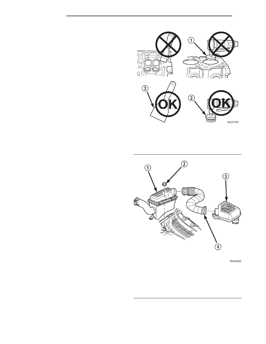
Never use the following to clean gasket surfaces:
• Metal scraper

• Abrasive pad or paper to clean cylinder block

and head

• High speed power tool with an abrasive pad or a

wire brush (Fig. 5)

Only use the following for cleaning gasket surfaces:
• Solvent or a commercially available gasket

remover

• Plastic or wood scraper (Fig. 5)

• Drill motor with 3M Roloc™ Bristle Disc (white

or yellow) (Fig. 5)

CAUTION: Excessive pressure or high RPM (beyond
the recommended speed), can damage the sealing
surfaces. The mild (white, 120 grit) bristle disc is
recommended. If necessary, the medium (yellow, 80
grit) bristle disc may be used on cast iron surfaces
with care.

REMOVAL

(1) Disconnect the battery cables. Remove the bat-

tery.

(2) Mark the hinge locations on the hood panel for

alignment reference during installation. Remove the
engine compartment lamp. Remove the hood.

WARNING: THE COOLANT IN A RECENTLY OPER-
ATED ENGINE IS HOT AND PRESSURIZED. USE
CARE TO PREVENT SCALDING BY HOT COOLANT.
CAREFULLY RELEASE THE PRESSURE BEFORE
REMOVING THE RADIATOR DRAIN COCK AND CAP.

(3) Drain the coolant (Refer to 7 - COOLING -

STANDARD PROCEDURE).

(4) Remove the air cleaner assembly, air in-let

hose and resonator assembly (Fig. 6).

(5) Recover refrigerant (if equipped with A/C).(Re-

fer to 24 - HEATING & AIR CONDITIONING/

PLUMBING

-

24

-

HEATING

&

AIR

CONDITIONING).

(6) Remove the radiator lower hose.

Fig. 5 PROPER TOOL USAGE FOR SURFACE

PREPARATION

1 - ABRASIVE PAD
2 - 3M ROLOC™ BRISTLE DISC
3 - PLASTIC/WOOD SCRAPER

Fig. 6 Air Cleaner and Resonator Removal and

Installation

1 - AIR CLEANER ASSEMBLY
2 - NUT AND WASHER
3 - RESONATOR ASSEMBLY
4 - AIR INLET HOSE

9 - 12

ENGINE 2.5L

AN

ENGINE 2.5L (Continued)

(7) Remove the radiator upper hose and coolant

recovery hose (Fig. 7).

(8) Remove the fan shroud (Fig. 7).

(9) Remove the radiator (Refer to 7 - COOLING/

ENGINE/RADIATOR - REMOVAL) and condenser
(Refer to 24 - HEATING & AIR CONDITIONING/
PLUMBING/A/C

CONDENSER

-

REMOVAL)

(if

equipped with air conditioning).

(10) Remove fan assembly and install a 5/16 x 1/2-

inch SAE capscrew through fan pulley into water
pump flange. This will maintain the pulley and
water pump in alignment when crankshaft is rotated.

(11) Disconnect the heater hoses.
(12) Disconnect the throttle cable, speed control

cable

(if

equipped)

and

transmission

cable

(if

equipped).

(13) Disconnect the body ground at the firewall.
(14) Disconnect the wires from the starter motor

solenoid.

(15) Disconnect all fuel injection harness connec-

tions.

WARNING: THE FUEL SYSTEM IS UNDER A CON-
STANT

PRESSURE

(EVEN

WITH

THE

ENGINE

TURNED OFF). BEFORE DISCONNECTING FUEL
LINES, THE FUEL SYSTEM PRESSURE MUST BE
RELEASED.

(16) Perform

fuel

pressure

release

procedure

(Refer to 14 - FUEL SYSTEM/FUEL DELIVERY -
STANDARD PROCEDURE).

(17) Disconnect the quick-connect fuel line at the

fuel rail (Refer to 14 - FUEL SYSTEM/FUEL DELIV-

ERY/QUICK CONNECT FITTING - STANDARD
PROCEDURE).

(18) Disconnect suction/discharge hose from A/C

compressor and cap off ports to prevent intrusion of
foreign material or refrigerant oil loss.

(19) Remove the power brake vacuum check valve

from the booster, if equipped.

(20) If equipped with power steering:

(a) Disconnect the power steering hoses from the

fittings at the steering gear.

(b) Drain the pump reservoir.
(c) Cap the fittings on the hoses and steering

gear to prevent foreign material from entering the
system.
(21) Identify, tag and disconnect all necessary wire

connectors and vacuum hoses.

(22) Raise the vehicle.
(23) Remove the oil filter.
(24) Remove the starter motor(Refer to 8 - ELEC-

TRICAL/STARTING/STARTER MOTOR - REMOV-
AL).

(25) Disconnect the exhaust pipe from the exhaust

manifold.

(26) Remove the flywheel housing access cover.
(27) Remove the upper flywheel and converter

housing bolts and loosen the bottom bolts.

(28) Remove the engine support cushion-to-engine

compartment bracket bolts.

(29) Remove the engine shock damper bracket

from the sill.

(30) Lower the vehicle.
(31) Attach a lifting device to the engine.
(32) Raise the engine slightly off the front sup-

ports.

(33) Place a support stand under the converter or

flywheel housing.

(34) Lift the engine out of the engine compartment

and install on an engine stand.

(35) Install the oil filter to keep foreign material

out of the engine.

INSTALLATION

(1) Remove the oil filter.
(2) Lift the engine off the stand and lower it into

the engine compartment. For easier installation, it
may be useful to remove the engine support cushions
from the engine support brackets as an aide for
alignment of the engine-to-transmission.

(3) Insert the transmission shaft into the clutch

spline. (M/T models)

(4) Align the flywheel housing with the engine.
(5) Install and tighten the flywheel housing lower

bolts.

(6) Install

the

engine

support

cushions

(if

removed).

Fig. 7 Upper Radiator Hose, Coolant Recovery Hose

& Fan Shroud

1 - UPPER RADIATOR HOSE
2 - FAN SHROUD
3 - COOLANT RECOVERY HOSE

AN

ENGINE 2.5L

9 - 13

ENGINE 2.5L (Continued)

(7) Lower the engine and engine support cushions

onto the engine compartment brackets.

(8) Remove the engine lifting device.
(9) Raise the vehicle.
(10) Install the converter-housing access cover.
(11) Install the exhaust pipe support.
(12) Install the starter motor (Refer to 8 - ELEC-

TRICAL/STARTING/STARTER MOTOR - INSTAL-
LATION).

(13) Tighten the engine support cushion through-

bolt nuts.

(14) Connect the exhaust pipe to the manifold.
(15) Install the oil filter.
(16) Lower the vehicle.
(17) Connect the coolant hoses and tighten the

clamps.

(18) If equipped with power steering:

(a) Remove the protective caps
(b) Connect the hoses to the fittings at the steer-

ing gear. Tighten the nut to 52 N·m (38 ft. lbs.)
torque.

(c) Fill the pump reservoir with fluid.

(19) Remove

the

pulley-to-water

pump

flange

alignment capscrew and install the fan assembly.

(20) Install the radiator (Refer to 7 - COOLING/

ENGINE/RADIATOR - INSTALLATION),condenser
(Refer to 24 - HEATING & AIR CONDITIONING/
PLUMBING/A/C CONDENSER - INSTALLATION)
(if equipped with air conditioning) and fan shroud.

(21) Connect the radiator hoses.
(22) Connect the oxygen sensor wire connector.
(23) Connect the throttle cable and install the rod.

Connect the transmission and speed control cables (if
equipped)

(24) Connect the fuel supply line to the injector

rail (Refer to 14 - FUEL SYSTEM/FUEL DELIVERY/
QUICK CONNECT FITTING - STANDARD PROCE-
DURE).

(25) Connect all the vacuum hoses and wire con-

nectors.

(26) Connect suction/discharge hose to compressor

(if equipped).

(27) Fill the power steering reservoir.
(28) Recharge air conditioning (Refer to 24 -

HEATING & AIR CONDITIONING/PLUMBING -
STANDARD PROCEDURE).

(29) Connect the battery cables.
(30) Install the resonator assembly, air in-let hose

and air cleaner (Fig. 6).

(31) Install the hood.
(32) Add engine oil and coolant.
(33) Start the engine and inspect for leaks.
(34) Stop the engine and check the fluid levels.

Add fluid, as required.

SPECIFICATIONS

2.5L ENGINE

ENGINE DESCRIPTION

DESCRIPTION

SPECIFICATION

Engine Type

In-line 4 Cylinder

Bore and Stroke

98.4 x 81.0 mm

(3.88 x 3.19 in.)

Displacement

2.5L (150 cu. in.)

Compression Ratio

9.1:1

Compression Pressure

Range

827 to 1,034 kPa

(120 to 150 psi)

Max. Variation Between

Cylinders

206 kPa (30 psi)

Firing Order

1–3–4–2

Lubrication

Pressure Feed–Full Flow

Filtration

Cooling System

Liquid Cooled–Forced

Circulation

Cylinder Block

Cast Iron

Crankshaft

Cast Nodular Iron

Cylinder Head

Cast Iron

Camshaft

Cast Iron

Pistons

Aluminum Alloy

Cylinder Combustion

Cavity

Double Quench

Connecting Rods

Cast Iron

CAMSHAFT

Hydraulic Tappet

Clearance

Zero Lash

Bearing Clearance

0.025 - 0.076 mm

(0.001 - 0.003 in.)

Bearing Journal Diameter

No. 1

51.54 - 51.56 mm

(2.029 - 2.030 in.)

No. 2

51.28 - 51.31 mm

9 - 14

ENGINE 2.5L

AN

ENGINE 2.5L (Continued)

DESCRIPTION

SPECIFICATION

(2.019 - 2.020 in.)

No. 3

51.03 - 51.05 mm

(2.009 - 2.010 in.)

No. 4

50.78 - 50.80 mm

(1.999 - 2.000 in.)

Base Circle Runout

(Max)

0.03 mm

(0.001 in.)

Camshaft Lobe Lift

Exhaust

6.579 mm (0.259 in.)

Intake

6.477 mm (0.255 in.)

Camshaft Duration

Intake

253.3°

Exhaust

259°

VALVES

Valve Lift

Exhaust

10.528 mm (0.4145 in.)

Intake

10.350 mm (0.4075 in.)

Intake Valve Timing

Opens

15.4° (BTDC)

Closes

58° (ABDC)

Duration

253.3°

Exhaust Valve Timing

Opens

52.8° (BBDC)

Closes

26.2° (ATDC)

Duration

259°

Valve Overlap

41.6°

Valve Lenght (Overall)

Intake

124.435 - 125.070 mm

(4.899 - 4.924 in.)

Exhaust

125.120 - 125.755 mm

(4.927 - 4.952 in.)

Valve Stem Diameter

7.899 - 7.925 mm

(0.311 - 0.312 in.)

Stem to Guide Clearance

0.025 - 0.076 mm

(0.001 - 0.003 in.)

ValveFace Angle

Intake

46.5°

DESCRIPTION

SPECIFICATION

Exhaust

46.5°

Valve Head Diameter

Intake

48.387 - 48.641 mm

(1.905 - 1.915 in.)

Exhaust

37.973 - 38.227 mm

(1.495 - 1.505 in.)

Tip Refinishing (Max

Alowable)

0.25 mm (0.010 in.)

VALVE SPRINGS

Free Length (Approx.)

47.65 mm (1.876 in.)

Spring Load

Valve Closed

316 to 351 N @ 41.656

mm

(71 to 79 Lbs. @ 1.64

in.)

Valve Open

898.6 to 969.7 N @

30.89 mm

(202 to 218 Lbs. @ 1.216

in.)

Inside Diameter (Top)

21.0 mm to 21.51 mm

(0.827 to 0.847 in.)

Installed Height

41.656 mm (1.640 in.)

CRANKSHAFT

End Play

0.038 to 0.165 mm

(0.0015 to 0.0065 in.)

Main Bearing Journal

Diameter

63.489 to 63.502 mm

(2.4996 to 2.5001 in.)

Main Bearing Journal

Width

No. 1

27.58 to 27.89 mm

(1.086 to 1.098 in.)

No. 2

32.28 to 32.33 mm

(1.271 to 1.273 in.)

No. 3-4-5

30.02 to 30.18 mm

(1.182 to 1.188 in.)

Main Bearing Clearance

0.03 to 0.06 mm

(0.001 to 0.0025 in.)

Main Bearing Clearance

AN

ENGINE 2.5L

9 - 15

ENGINE 2.5L (Continued)


Content   ..  454  455  456  457   ..