Dodge Dakota (R1). Manual - part 269


  Index      Dodge     Dodge Dakota (R1) - service repair manual 2000 year


Search            


Content   ..  267  268  269  270   ..


Dodge Dakota (R1). Manual - part 269


WARNING: USE EXTREME CAUTION WHEN THE
ENGINE IS OPERATING. DO NOT STAND IN A
DIRECT LINE WITH THE FAN. DO NOT PUT YOUR
HANDS NEAR THE PULLEYS, BELTS OR FAN. DO
NOT WEAR LOOSE CLOTHING.

(5) Start the engine and operate at 2400 rpm.

Within ten minutes the air temperature (indicated on
the dial thermometer) should be up to 93° C (200° F).
Fan drive engagement should have started to occur
at between 82° to 91° C (180° to 195° F). Engage-
ment is distinguishable by a definite increase in fan
flow noise (roaring).

(6) When the air temperature reaches 93° C (200°

F), remove the plastic sheet. Fan drive disengage-
ment 
should have started to occur at between 57° to
79° C (135° to 175° F). A definite decrease of fan
flow noise (roaring) should be noticed. If not, replace
the defective viscous fan drive unit.

WATER PUMP

DESCRIPTION

A

centrifugal

water

pump

circulates

coolant

through the water jackets, passages, water manifold,
radiator core, pressurized coolant tank, cooling sys-
tem hoses and heater core. The pump is driven from
the engine crankshaft by a drive belt. The water
pump is bolted to the water pump adapter (Fig. 16).
The water pump adapter is bolted to the engine.

The water pump impeller is pressed onto the rear

of a shaft that rotates in bearings pressed into the
housing. The bottom of the housing is equipped with
a small vent tube (Fig. 16)to allow seepage to escape.
A drain hose is attached to this tube. The water
pump seals is lubricated by the antifreeze in the cool-
ant mixture. No additional lubrication is necessary.

A rubber o-ring (instead of a gasket) is used as a

seal between the water pump and the water pump
adapter (Fig. 16).

A quick test to determine if the pump is working is

to check if the heater warms properly. A defective
water pump will not be able to circulate heated cool-
ant through the heater hoses and the heater core.

REMOVAL

The water pump can be removed without discharg-

ing the air conditioning system (if equipped).

The water pump is serviced by replacing the pump

and its impeller only. The water pump adapter (Fig.
17) does not have to be removed. The pump impeller
is pressed on the rear of the pump shaft and bearing
assembly. The pump is serviced only as a complete
assembly with the impeller, housing, hub and bear-
ing.

A rubber o-ring seal (instead of a gasket) is used as

a seal between the water pump and the water pump
adapter.

WARNING:

DO

NOT

REMOVE

THE

CYLINDER

BLOCK DRAIN-PLUG, THE COOLANT TANK CAP,
THE RADIATOR FILL VENT VALVE, OR LOOSEN
THE RADIATOR DRAINCOCK WITH THE SYSTEM
HOT AND PRESSURIZED. SERIOUS BURNS FROM
THE COOLANT CAN OCCUR.

DO NOT WASTE reusable coolant. If the solution

is clean, drain coolant into a clean container for
reuse.

(1) Disconnect the negative battery cable.

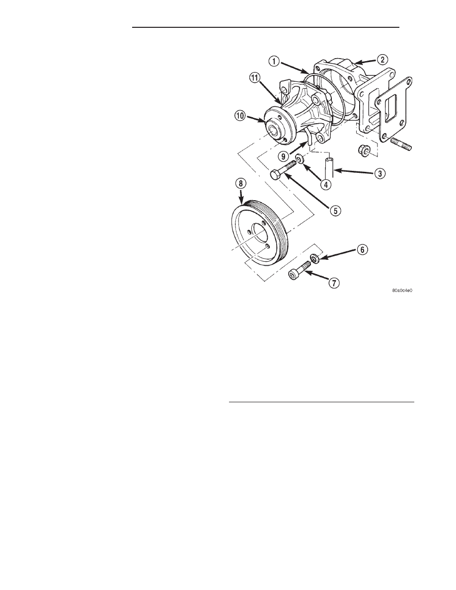
Fig. 16 Water Pump— Typical

1 - O-RING SEAL
2 - WATER PUMP ADAPTER
3 - DRAIN HOSE
4 - WASHER
5 - PUMP MOUNTING BOLTS (4)
6 - WASHER
7 - WATER PUMP PULLEY BOLTS (3)
8 - WATER PUMP PULLEY
9 - VENT TUBE
10 - PUMP HUB
11 - WATER PUMP

7a - 22

2.5L VM DIESEL

R1

VISCOUS FAN DRIVE (Continued)

(2) Drain the cooling system (Refer to 7 - COOL-

ING/ENGINE - STANDARD PROCEDURE).

(3) Remove the coolant bypass hose from the top of

the radiator and position out of the way.

(4) Remove the refrigerant line bracket retaining

bolt from the water manifold. This will allow some
refrigerant line movement to ease access to the water
pump.

(5) Remove the intercooler inlet and outlet hoses

from the intercooler and position them out of the
way.

(6) Remove the air filter assembly from the vehi-

cle.

(7) Loosen but do not remove the 3 water pump

pulley bolts (Fig. 17).

(8) Remove the accessory drive belt from the water

pump pulley (Refer to 7 - COOLING/ACCESSORY
DRIVE/DRIVE BELTS - REMOVAL).

WARNING: CONSTANT TENSION HOSE CLAMPS
ARE USED ON MOST COOLING SYSTEM HOSES.
WHEN REMOVING OR INSTALLING, USE ONLY
TOOLS DESIGNED FOR SERVICING THIS TYPE OF
CLAMP

(Fig.

18).

ALWAYS

WEAR

SAFETY

GLASSES WHEN SERVICING CONSTANT TENSION
CLAMPS.

CAUTION: A number or letter is stamped into the
tongue of constant tension clamps (Fig. 19). If
replacement is necessary, use only an original
equipment clamp with matching number or letter.

(9) A metal coolant tube (used to connect rubber

coolant hoses), and its mounting bracket are attached
to the front of the water pump (Fig. 20). Remove the
(2) tube assembly bracket retaining bolts.

(10) Disconnect the coolant hose from the metal

coolant tube (Fig. 20).

(11) Remove the 3 water pump pulley bolts (Fig.

17).

(12) Remove the water pump pulley from the

water pump.

(13) Disconnect the drain hose from the vent tube

at the bottom of water pump (Fig. 17).

(14) Remove the water pump mounting bolts (Fig.

17).

(15) Remove the water pump from engine.

INSPECTION

Replace the water pump assembly if it has any of

the following conditions:

• The body is cracked or damaged

Fig. 17 Water Pump Configuration

1 - O-RING SEAL
2 - WATER PUMP ADAPTER
3 - DRAIN HOSE
4 - WASHER
5 - PUMP MOUNTING BOLTS (4)
6 - WASHER
7 - WATER PUMP PULLEY BOLTS (3)
8 - WATER PUMP PULLEY
9 - VENT TUBE
10 - PUMP HUB
11 - WATER PUMP

Fig. 18 Hose Clamp Tool

1 - HOSE CLAMP TOOL 6094
2 - HOSE CLAMP

R1

2.5L VM DIESEL

7a - 23

WATER PUMP (Continued)

• Water leaks from the shaft seal. This is evident

by traces of coolant below the vent tube drain hose

• Loose or rough turning bearing.

• Impeller rubs either the water pump body or

water pump adapter.

INSTALLATION

(1) Clean the o-ring mating surfaces. If the original

pump is to be reinstalled, remove any deposits or other
foreign material. Inspect the water pump and water
pump adapter mating surfaces for erosion (Fig. 17).

(2) Position a new rubber o-ring seal between the

pump and pump adapter (Fig. 17). Use petroleum
jelly to hold the o-ring in position during assembly.

(3) Position the pump on the engine.
(4) Position the metal coolant tube and its mount-

ing bracket on the pump.

(5) Install the water pump mounting bolts (Fig.

17). Torque bolts to 24 N·m (18 ft. lbs.).

(6) Install drain hose on the vent tube at bottom of

pump (Fig. 17).

(7) Position the water pump pulley on the water

pump (Fig. 17).

(8) Install the water pump pulley bolts finger tight

(Fig. 17).

(9) Connect the rubber coolant hose on the metal

coolant tube.

(10) Install the accessory drive belt (Refer to 7 -

COOLING/ACCESSORY

DRIVE/DRIVE

BELTS

-

INSTALLATION).

(11) Torque the water pump pulley retaining bolts

to 24 N·m (18 ft. lbs.).

(12) Position and install the intercooler inlet and

outlet hoses on the intercooler.

(13) Position and install the coolant bypass hose

on the top of the radiator.

(14) Position and install the refrigerant line sup-

port bracket bolt on the water manifold.

(15) Install the air filter assembly on the vehicle.
(16) Fill the cooling system with coolant and check

for leaks (Refer to 7 - COOLING/ENGINE - STAN-
DARD PROCEDURE).

(17) Connect the negative battery cable.
(18) Start and warm the engine. Check for leaks.

COOLANT TANK

DESCRIPTION

A pressurized, plastic coolant tank is used with this

cooling system (Fig. 21). The tank is located at the
rear of the engine compartment and is mounted as the
highest point of the cooling system. This allows any
air or vapor exceeding the pressure/vent cap rating to
escape through the cap. Coolant flows through the
tank at all times during engine operation whether the
engine is cold or at normal operating temperature.
The coolant tank is equipped with a threaded pres-
sure/vent cap (Refer to 7 - COOLING/ENGINE/RADI-
ATOR PRESSURE CAP - DESCRIPTION).

The low coolant level sensor is located near the

bottom of the tank (Fig. 21).

Fig. 19 Clamp Number/Letter Location

1 - TYPICAL CONSTANT TENSION HOSE CLAMP
2 - CLAMP NUMBER/LETTER LOCATION
3 - TYPICAL HOSE

Fig. 20 Coolant Tube at Water Pump

1 - COOLANT TUBE
2 - WATER PUMP
3 - BRACKET

7a - 24

2.5L VM DIESEL

R1

WATER PUMP (Continued)

REMOVAL

WARNING: Engine coolant can reach temperatures
of 200° Fahrenheit or greater. If the cooling system
is opened with coolant at a high temperature, hot
coolant can be forced out of the system under high
pressures, causing personal injury. Allow system to
cool down prior to removing the pressure cap.

(1) Disconnect the negative battery cable.
(2) Remove both of the wiper arms from the vehi-

cle. Refer to Wiper and Washer Systems for the pro-
cedure.

(3) Raise the vehicle on the hoist.
(4) Remove the lower front splash shield.
(5) Drain the cooling system (Refer to 7 - COOL-

ING/ENGINE - STANDARD PROCEDURE).

(6) Lower the vehicle on the hoist.
(7) Remove the cowl grille (Fig. 22) (Refer to 23 -

BODY/EXTERIOR/COWL GRILLE - REMOVAL).

(8) Remove the coolant overflow hoses from the

coolant reservoir (Fig. 23).

(9) Remove the coolant supply hoses from the

water manifold (Fig. 23).

(10) Remove the EGR solenoid from the coolant

reservoir (Fig. 23).

(11) Disconnect the coolant level sensor electrical

connector (Fig. 23).

(12) Remove the coolant reservoir retaining bolts

from inside the cowl panel (Fig. 23).

(13) Disconnect the coolant supply hoses from the

coolant reservoir (Fig. 23).

(14) Remove the coolant reservoir from the vehicle.

Fig. 21 Pressurized Coolant Tank

1 - COOLANT RESERVE/OVERFLOW TANK
2 - FUEL HEATER/WATER SEPARATOR

3 - HYDRAULIC CLUTCH FLUID RESERVOIR
4 - LOW COOLANT LEVEL SWITCH

R1

2.5L VM DIESEL

7a - 25

COOLANT TANK (Continued)


Content   ..  267  268  269  270   ..