Dodge Dakota (R1). Manual - part 268


  Index      Dodge     Dodge Dakota (R1) - service repair manual 2000 year


Search            


Content   ..  266  267  268  269   ..


Dodge Dakota (R1). Manual - part 268


RADIATOR COOLANT FLOW
CHECK

DIAGNOSIS AND TESTING - RADIATOR
COOLANT FLOW

There is coolant flow through the coolant tank (bot-

tle) before and after the thermostat opens.

CAUTION: Do not remove the vent valve to insert a
temperature gauge thought the opening , coolant
will spill out of the system and the engine will not
be filled with coolant up to the heads. Major dam-
age could happen if you run the engine in this con-
dition.

RADIATOR PRESSURE/VENT
CAP

DESCRIPTION

The pressure/vent cap is threaded-on to the coolant

tank. This cap releases excess pressure at some point
within a range of 90-117 kPa (13- 17 psi). The actual
pressure relief point (in pounds) is labeled on top of
the cap (Fig. 12).

The cooling system will operate at pressures

slightly above atmospheric pressure. This results in a
higher coolant boiling point allowing increased radi-
ator cooling capacity. The cap (Fig. 12) contains a
spring-loaded pressure relief valve. This valve opens
when system pressure reaches approximately 110
kPa (16 psi).

When the engine is cooling down, vacuum is

formed within the cooling system. To prevent collapse
of the radiator and coolant hoses from this vacuum, a
vacuum valve is used within the cap. This valve pre-
vents excessive pressure differences from occurring
between the closed cooling system and the atmo-
sphere. If the vacuum valve is stuck shut, the radia-
tor and/or cooling system hoses will collapse on cool-
down.

NOTE: Do not use any type of tool when tightening
the cap. Hand tighten only (approximately 5 N·m or
44 in. lbs.) torque.

DIAGNOSIS AND TESTING - RADIATOR
PRESSURE CAP

Remove the cap from the coolant tank. Be sure

that sealing surfaces are clean. Moisten rubber gas-
ket with water.

A two-piece, threaded adapter set (Fig. 5) must be

used to adapt a standard pressure-type tester (Fig. 6)
when testing either the coolant tank or pressure cap.
Use Kent-Moore

t adapter set number J-24460-92 or

Snap-On

t numbers TA-32 and TA-33. Attach the

adapter to the cap. Adapter must first be threaded to
cap. Attach pressure tester to adapter.

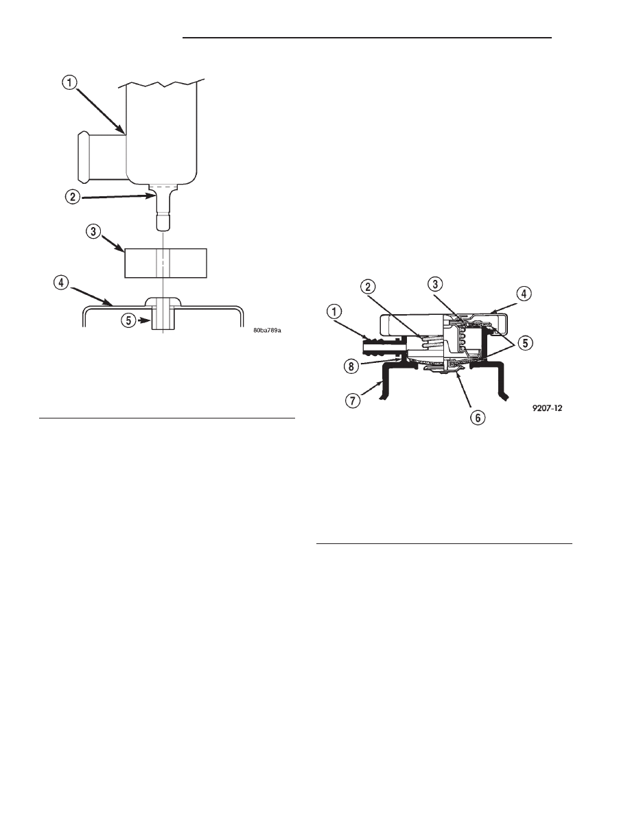
Fig. 11 Radiator Alignment Dowels

1 - RADIATOR
2 - ALIGNMENT DOWEL
3 - RADIATOR LOWER ISOLATOR
4 - RADIATOR LOWER CROSSMEMBER
5 - RUBBER GROMMET

Fig. 12 Coolant Tank Pressure/Vent Cap

1 - OVERFLOW NIPPLE
2 - MAIN SPRING
3 - GASKET RETAINER
4 - STAINLESS-STEEL SWIVEL TOP
5 - RUBBER SEALS
6 - VENT VALVE
7 - PRESSURE BOTTLE
8 - FILLER NECK

7a - 18

2.5L VM DIESEL

R1

RADIATOR (Continued)

Operate the tester pump and observe the gauge

pointer at its highest point. The cap release pressure
should be 90-to-117 kPa (13-to-17 psi). The cap is sat-
isfactory when the pressure holds steady. It is also
good if it holds pressure within the 90-to-117 kPa
(13-to-17 psi) range for 30 seconds or more. If the
pointer drops quickly, replace the cap.

CAUTION: Radiator pressure testing tools are very
sensitive to small air leaks, which will not cause
cooling system problems. A pressure cap that does
not have a history of coolant loss should not be
replaced just because it leaks slowly when tested
with this tool. Add water to tool. Turn tool upside
down and recheck pressure/vent cap to confirm
that cap needs replacement.

INSPECTION

Visually inspect the gasket on the cap. Replace cap

if the gasket is swollen, torn or worn. Inspect the
area around the coolant tank filler neck for white
deposits that indicate a leaking cap.

The cap must be replaced by a similar threaded-on

unit with the correct operating pressures if replace-
ment is necessary.

THERMOSTAT

DESCRIPTION

A pellet-type thermostat controls the operating

temperature of the engine by controlling the amount
of coolant flow to the radiator.

OPERATION

The thermostat starts to open at 80°C (176°F).

Above this temperature, coolant is allowed to flow to
the radiator. This provides quicker engine warmup
and overall temperature control.

The same thermostat is used for winter and sum-

mer seasons. An engine should not be operated with-
out a thermostat, except for servicing or testing.
Operating without a thermostat causes other prob-
lems. These are: longer engine warmup time, unreli-
able

warmup

performance,

increased

exhaust

emissions and crankcase condensation. This conden-
sation can result in sludge formation.

CAUTION: Do not operate an engine without a ther-
mostat, except for servicing or testing.

DIAGNOSIS AND TESTING - THERMOSTAT

Diesel engines, due to their inherent efficiency are

slower to warm up than gasoline powered engines,
and will operate at lower temperatures when the

vehicle is unloaded. Because of this, lower tempera-
ture

gauge

readings

for

diesel

versus

gasoline

engines may, at times be normal.

NOTE: The DRB scan tool cannot be used to mon-
itor engine coolant temperature on the diesel
engine.

(1) To determine if the thermostat is defective, it

must be removed from the vehicle (Refer to 7 -
COOLING/ENGINE/THERMOSTAT

HOUSING

-

REMOVAL).

(2) After the thermostat has been removed, exam-

ine the thermostat and inside of thermostat housing
for contaminants. If contaminants are found, the
thermostat may already be in a “stuck open” position.
Flush the cooling system before replacing thermostat
(Refer to 7 - COOLING/ENGINE - CLEANING).

(3) Place the thermostat into a container filled

with water.

(4) Place the container on a hot plate or other suit-

able heating device.

(5) Place a commercially available radiator ther-

mometer into the water.

(6) Apply heat to the water while observing the

thermostat and thermometer.

(7) When the water temperature reaches 80°C

(176°F) the thermostat should start to open (valve
will start to move). If the valve starts to move before
this temperature is reached, it is opening too early.
Replace thermostat. The thermostat should be fully
open (valve will stop moving) at approximately 89°C
(192°F). If the valve is still moving after the water
temperature reaches this temperature, it is opening
too late. Replace thermostat.

(8) If the valve refuses to move at any time,

replace thermostat.

REMOVAL

WARNING:

DO

NOT

REMOVE

THE

CYLINDER

BLOCK DRAIN-PLUG, THE COOLANT TANK CAP,
THE RADIATOR FILL VENT VALVE, OR LOOSEN
THE RADIATOR DRAINCOCK WITH THE SYSTEM
HOT AND PRESSURIZED. SERIOUS BURNS FROM
THE COOLANT CAN OCCUR.

DO NOT WASTE reusable coolant. If the solution

is clean, drain the coolant into a clean container for
reuse.

(1) Drain the coolant from the radiator until the

level is below the thermostat housing (Refer to 7 -
COOLING/ENGINE - STANDARD PROCEDURE).

R1

2.5L VM DIESEL

7a - 19

RADIATOR PRESSURE/VENT CAP (Continued)

WARNING: CONSTANT TENSION HOSE CLAMPS
ARE USED ON MOST COOLING SYSTEM HOSES.
WHEN REMOVING OR INSTALLING, USE ONLY
TOOLS DESIGNED FOR SERVICING THIS TYPE OF
CLAMP. ALWAYS WEAR SAFETY GLASSES WHEN
SERVICING CONSTANT TENSION CLAMPS.

CAUTION: A number or letter is stamped into the
tongue of constant tension clamps. If replacement
is necessary, use only an original equipment clamp
with matching number or letter.

(2) Remove the upper radiator hose at the thermo-

stat housing (Fig. 13).

(3) Remove the (2) refrigerant line support bracket

bolts from the generator mounting bracket and the
water manifold. Gently position the refrigerant lines
out of the way to access the thermostat housing
bolts.

(4) Remove the four thermostat housing bolts (Fig.

14)

(5) Remove the thermostat housing from the water

manifold.

(6) Remove the thermostat and rubber seal from

the water manifold.

(7) Thoroughly clean the rubber seal mating sur-

faces.

INSTALLATION

(1) Install a new rubber seal around the outer lip

of the thermostat (a notch is provided in the rubber
seal). Do not apply any adhesive to this seal.

(2) Install the replacement thermostat and rubber

seal as one assembly into the water manifold adapter
(the pointed end of the thermostat should be facing
towards the front of engine (Fig. 14). Observe the
recess groove in the water manifold adapter. Be sure
the thermostat vent is in the 12 o’clock position (Fig.
14).

(3) Position the thermostat housing and four bolts

to the water manifold.

CAUTION:

Tightening

the

thermostat

housing

unevenly or with the thermostat out of its recess
groove, may result in a cracked housing.

(4) Tighten the four housing bolts to 11 N·m (98

in. lbs.) torque.

(5) Install the refrigerant line support bracket

bolts in there original positions. Torque the bolts to
20 N·m (177 in. lbs.).

(6) Install the radiator hose on thermostat housing

(Fig. 13).

Fig. 13 Upper Radiator Hose – 2.5 Diesel

1 - 1/2 DRIVE BREAKER BAR OR RATCHET
2 - UPPER RADIATOR HOSE
3 - FAN SHROUD

Fig. 14 Thermostat Removal/Installation

1 - THERMOSTAT RECESS GROOVE
2 - WATER MANIFOLD ADAPTER
3 - THERMOSTAT
4 - THERMOSTAT HOUSING
5 - HOUSING BOLTS (4)
6 - WASHER
7 - RUBBER SEAL
8 - VENT

7a - 20

2.5L VM DIESEL

R1

THERMOSTAT (Continued)

(7) Be sure that the radiator drain is tightly

closed. Fill the cooling system to the correct level
with the required coolant mixture (Refer to 7 -
COOLING/ENGINE - STANDARD PROCEDURE).

(8) Start the engine and check for leaks.

VISCOUS FAN DRIVE

DESCRIPTION

The thermal viscous fan drive (Fig. 15) is a sili-

cone-fluid-filled coupling. It connects the fan blade
assembly to the fan pulley.

OPERATION

The coupling allows the fan to be driven in a nor-

mal manner. This is done at low engine speeds while
limiting the top speed of the fan to a predetermined
maximum level at higher engine speeds. A bimetallic
coil spring is located on the front face. This spring
coil reacts to the temperature of the radiator dis-
charge air. It engages the viscous fan drive for higher
fan speed if the air temperature from the radiator
rises above a certain point. Until additional engine
cooling is necessary, the fan will remain at a reduced
rpm regardless of engine speed.

The viscous fan drive will only engage when suffi-

cient heat is present. This is when the air flowing
through the radiator core causes a reaction from the
bimetallic coil. It then increases fan speed to provide
the necessary additional engine cooling.

Once the engine has cooled, the radiator discharge

temperature will drop. The bimetallic coil again
reacts and the fan speed is reduced to the previous
disengaged speed.

CAUTION: Some engines equipped with serpentine
drive belts have reverse rotating fans and viscous
fan

drives.

They

are

marked

with

the

word

REVERSE to designate their usage. Installation of
the wrong fan or viscous fan drive can result in
engine overheating.

NOISE

NOTE: It is normal for fan noise to be louder (roar-
ing) when:

• The underhood temperature is above the engage-

ment point for the viscous drive coupling. This may
occur when ambient (outside air temperature) is very
high.

• Engine loads and temperatures are high such as

when towing a trailer.

• Cool silicone fluid within the fan drive unit is

being redistributed back to its normal disengaged
(warm) position. This can occur during the first 15
seconds to one minute after engine start-up on a cold
engine.

LEAKS

Viscous fan drive operation is not affected by small

oil stains near the drive bearing. If leakage appears
excessive, replace the fan drive unit.

DIAGNOSIS AND TESTING - VISCOUS FAN
DRIVE

If the fan assembly free-wheels without drag (the

fan blades will revolve more than five turns when
spun by hand), replace the fan drive. This spin test
must be performed when the engine is cool.

The cooling system must be in good condition. This

is checked prior to performing the following test. It
also will ensure against excessively high coolant tem-
perature.

WARNING: BE SURE OF ADEQUATE FAN BLADE
CLEARANCE BEFORE DRILLING.

(1) Drill a 3.12-mm (1/8-in) diameter hole in the

top center of the fan shroud.

(2) Obtain a dial thermometer with an 8 inch stem

(or equivalent). It should have a range of -18°-to-
105°C (0°-to-220° F). Insert thermometer through the
hole in the shroud. Be sure that there is adequate
clearance from the fan blades.

(3) Block the air flow through the radiator. Secure

a sheet of plastic in front of the radiator (or air con-
ditioner condenser). Use tape at the top to secure the
plastic and be sure that the air flow is blocked.

(4) Be sure that the air conditioner (if equipped) is

turned off.

Fig. 15 Viscous Fan Drive

1 - MOUNTING NUT TO FAN PULLEY SHAFT
2 - THERMOSTATIC SPRING
3 - VISCOUS FAN DRIVE

R1

2.5L VM DIESEL

7a - 21

THERMOSTAT (Continued)


Content   ..  266  267  268  269   ..