Dodge Dakota (R1). Manual - part 267


  Index      Dodge     Dodge Dakota (R1) - service repair manual 2000 year


Search            


Content   ..  265  266  267  268   ..


Dodge Dakota (R1). Manual - part 267


STANDARD PROCEDURE - COOLANT
REPLACEMENT

It is recommended that the cooling system be

drained and flushed at 84,000 kilometers (52,500
miles), or 3 years, whichever occurs first. Then every
two years, or 48,000 kilometers (30,000 miles),
whichever occurs first.

STANDARD PROCEDURE - COOLANT LEVEL
CHECK

The coolant level is checked and adjusted at the

pressurized coolant tank (Fig. 7). The tank is located
at the right-rear side of the engine compartment and
is mounted as the highest point of the cooling sys-
tem. This will allow any air or vapor exceeding the
pressure/vent cap rating to escape through the cap.
The coolant tank is equipped with a threaded-on
pressure/vent cap (Refer to 7 - COOLING/ENGINE/
RADIATOR PRESSURE CAP - DESCRIPTION).

A coolant reserve/overflow system with a separate

tank is not used with the 2.5L diesel engine.

(1) Add coolant into the coolant tank up to the

COLD mark. If possible, only add coolant when

the engine is cold. Coolant level in a warm
engine will be higher in the tank due to ther-
mal expansion.

(2) After the engine has been operated through a

few heat-up and cool-down cycles, recheck the coolant
level in the tank.

FAN BLADE

REMOVAL

Accessory drive belt removal is not necessary for

fan blade or viscous fan drive removal.

(1) Disconnect negative battery cable from battery.
(2) The thermal viscous fan drive/fan blade assem-

bly is attached (threaded) to the fan pulley shaft
(Fig. 8). Remove fan blade/viscous fan drive assembly
from fan pulley by turning mounting nut counter-
clockwise as viewed from front. Threads on viscous
fan drive are RIGHT HAND. Snap-On

t 36 MM Fan

Wrenches (number SP346) can be used to turn the
mounting nut and to hold the fan pulley from rotat-
ing.

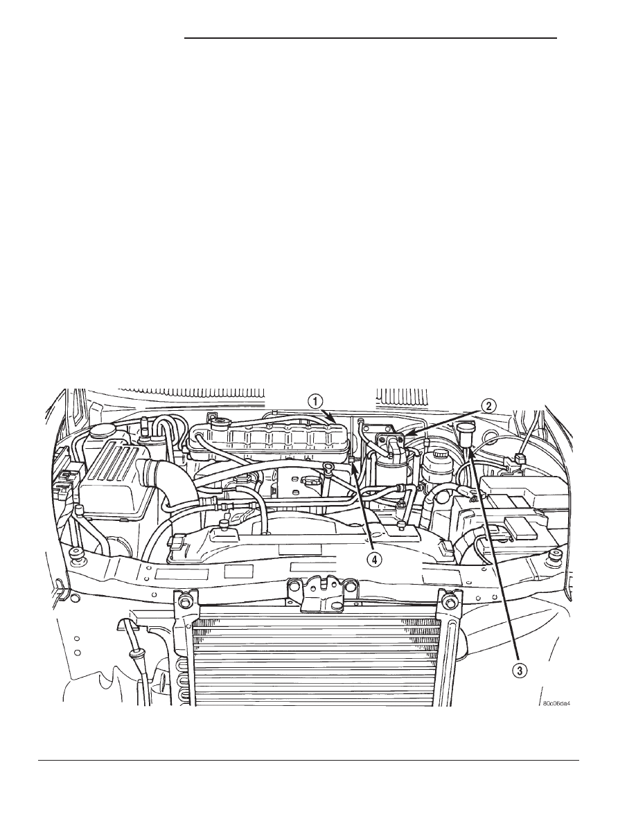
Fig. 7 Coolant Tank and Pressure/Vent Cap

1 - COOLANT RESERVE/OVERFLOW TANK
2 - FUEL HEATER/WATER SEPARATOR

3 - HYDRAULIC CLUTCH FLUID RESERVOIR
4 - LOW COOLANT LEVEL SWITCH

7a - 14

2.5L VM DIESEL

R1

COOLANT (Continued)

(3) Do not attempt to remove fan/viscous fan drive

assembly from vehicle at this time.

(4) Do not unbolt fan blade assembly from viscous

fan drive at this time.

(5) Remove the fan shroud mounting bolts.
(6) Remove the fan shroud and fan blade/viscous

fan drive assembly as a complete unit from vehicle.

(7) After removing fan blade/viscous fan drive

assembly, do not place viscous fan drive in horizon-
tal position. If stored horizontally, silicone fluid in
the viscous fan drive could drain into its bearing
assembly and contaminate lubricant.

CAUTION: Do not attempt to remove the fan pulley
bolts. The fan pulley is under tension from the drive
belt.Remove four bolts securing fan blade assembly
to viscous fan drive (Fig. 8).

INSPECTION

The fan cannot be repaired. If fan is damaged, it

must be replaced. Inspect fan as follows:

(1) Remove fan blade and viscous fan drive as an

assembly from the engine (Fig. 8).

(2) Remove fan blade assembly from viscous fan

drive unit (four bolts).

(3) Lay fan on a flat surface with leading edge fac-

ing down. With tip of blade touching flat surface,
replace fan if clearance between opposite blade and
surface is greater than 2.0 mm (.090 inch). Rocking
motion of opposite blades should not exceed 2.0 mm
(.090 inch). Test all blades in this manner.

WARNING:

DO

NOT

ATTEMPT

TO

BEND

OR

STRAIGHTEN FAN BLADES IF NOT WITHIN SPECI-
FICATIONS.

(4) Inspect fan assembly for cracks, bends, loose

rivets or broken welds. Replace fan if any damage is
found.

CAUTION:

If

fan

blade

assembly

is

replaced

because of mechanical damage, the fan pulley bear-
ing and viscous fan drive should also be inspected.
These components could have been damaged due
to excessive vibration.

CAUTION: Some engines equipped with serpentine
drive belts have reverse rotating fans and viscous
fan

drives.

They

are

marked

with

the

word

REVERSE to designate their usage. Installation of
the wrong fan or viscous fan drive can result in
engine overheating.

INSTALLATION

(1) Install fan blade assembly to viscous fan drive.

Tighten bolts (Fig. 8) to 23 N·m (200 in. lbs.) torque.

(2) Position fan shroud and fan blade/viscous fan

drive assembly to vehicle as a complete unit.

(3) Install and tighten fan shroud bolts to 3 N·m

(31 in. lbs.) torque.

(4) Install fan blade/viscous fan drive assembly to

fan pulley shaft (Fig. 8).

(5) Connect the negative battery cable.

Fig. 8 Thermal Viscous Fan Drive and Blade

Assembly

1 - FAN PULLEY
2 - FAN DRIVE-TO-FAN BLADE BOLTS (4)
3 - MOUNTING NUT
4 - THERMAL VISCOUS FAN DRIVE
5 - FAN BLADES
6 - FAN PULLEY SHAFT
7 - WATER PUMP

R1

2.5L VM DIESEL

7a - 15

FAN BLADE (Continued)

LOW COOLANT LEVEL
SWITCH

DESCRIPTION

The low coolant level sensor checks for low coolant

level in the coolant tank. A signal will be sent from
this sensor to the powertrain control module (PCM).
When the PCM determines low coolant level, the
instrument panel mounted low coolant level warning
lamp will be illuminated. The sensor is located on the
front side of the coolant tank (Fig. 9). For informa-
tion, refer to Instrument Panel and Gauges.

If this lamp is illuminated, it indicates the need for

service.

RADIATOR

DESCRIPTION

The radiator used with the 2.5L diesel is con-

structed of a horizontal down-flow aluminum core
with plastic side tanks.

CAUTION: Plastic tanks, while stronger than brass,
are

subject

to

damage

by

impact,

such

as

wrenches.

REMOVAL

On 2.5L turbo diesel engine equipped vehicles, the

charge air cooler (intercooler) is bolted to and sup-
ported by the radiator. If either one of these compo-
nents requires replacement they must be removed
from the vehicle as an assembly and separated on a
bench.

WARNING: Engine coolant can reach temperatures
of 200° Fahrenheit or greater. If the cooling system
is opened with coolant at a high temperature, hot
coolant can be forced out of the system under high
pressures, causing serious personal injury. Allow
system to cool down prior to removing the pressure
cap.

Fig. 9 Low Coolant Level Sensor

1 - COOLANT RESERVE/OVERFLOW TANK
2 - FUEL HEATER/WATER SEPARATOR

3 - HYDRAULIC CLUTCH FLUID RESERVOIR
4 - LOW COOLANT LEVEL SWITCH

7a - 16

2.5L VM DIESEL

R1

NOTE: Note the location of all factory installed air
seals. These seals are used at the top, bottom and
sides of the radiator and/or charge air cooler to
guide the flow of air through these components to
promote cooling. To prevent overheating these
seals must be reinstalled in there original positions
after service.

(1) Disconnect the negative battery cable.
(2) Raise the vehicle on the hoist.
(3) Remove the lower front splash shield
(4) Drain the cooling system (Refer to 7 - COOL-

ING/ENGINE - STANDARD PROCEDURE).

(5) Remove the lower radiator hose from the radi-

ator.

(6) Remove the (2) lower fan shroud retaining

bolts.

(7) Lower the vehicle from the hoist.

(8) Remove the upper radiator support retaining

bolts (Fig. 10)and remove the support from the vehi-
cle.

(9) Remove the upper radiator hose from the radi-

ator (Fig. 10).

(10) Remove the coolant overflow hose from the

radiator.

(11) Remove the (2) upper fan shroud retaining

bolts and position the fan assembly out of the way
(Fig. 10).

(12) Disconnect the charge air cooler inlet and out-

let hoses from the charge air cooler.

(13) Position the air deflectors out of the way.
(14) Remove the radiator and intercooler by lifting

straight up and out of the engine compartment.

(15) Place the assembly on a bench and separate

the intercooler from the radiator by removing the
retaining bolts.

CLEANING

The radiator and air conditioning fins should be

cleaned when an accumulation of bugs, leaves etc.
has occurred. Clean radiator fins are necessary for
good heat transfer. With the engine cold, apply cold
water and compressed air to the back (engine side) of
the radiator to flush the radiator and/or A/C con-
denser of debris.

INSTALLATION

(1) Install the intercooler on the radiator. Torque

the bolts to 25 N·m (221in. lbs.).

CAUTION: Care must be taken not to damage the
radiator / intercooler cooling fins during installation.
This will decrease the components cooling capabil-
ity and/or cause leaks.

(2) Position the radiator and intercooler in the

vehicle. Making sure the rubber insulators are
installed on the radiator lower mounting dowels and
inserted through the holes in the lower crossmember
(Fig. 11).

(3) Position air deflectors in there original posi-

tions (Fig. 10).

(4) Install the upper radiator support (Fig. 10).

Torque bolts to 20 N·m (177 in. lbs.).

(5) Install the coolant overflow hose on the radia-

tor.

(6) Install the upper radiator hose on the radiator

(Fig. 10).

(7)

Position the fan shroud assembly and install

the (2) upper fan shroud retaining bolts (Fig. 10).
Torque bolts to 12 N·m (105in. lbs.).

(8) Install the intercooler inlet and outlet hoses on

the intercooler.

(9) Raise the vehicle on the hoist.
(10) Install the (2) lower fan shroud retaining

bolts. Torque the bolts to 12 N·m (105in. lbs.).

(11) Install the lower radiator hose on the radiator.
(12) Install the lower front splash shield
(13) Lower the vehicle on the hoist.
(14) Fill the cooling system (Refer to 7 - COOL-

ING/ENGINE - STANDARD PROCEDURE).

(15) Connect the negative battery cable.

Fig. 10 Upper Radiator Support

1 - UPPER RADIATOR SUPPORT RETAINING BOLTS
2 - FRONT CLOSURE PANEL
3 - UPPER FAN SHROUD RETAINING BOLTS
4 - UPPER RADIATOR HOSE

R1

2.5L VM DIESEL

7a - 17

RADIATOR (Continued)


Content   ..  265  266  267  268   ..