Dodge Dakota (R1). Manual - part 270


  Index      Dodge     Dodge Dakota (R1) - service repair manual 2000 year


Search            


Content   ..  268  269  270  271   ..


Dodge Dakota (R1). Manual - part 270


INSTALLATION

(1) Position the coolant reservoir and connect the

coolant supply hoses (Fig. 22).

(2) Install the coolant reservoir retaining bolts

from inside the cowl panel (Fig. 22). Torque bolts to
12 N·m (106 in. lbs.).

(3) Connect the coolant level sensor electrical con-

nector (Fig. 22).

(4) Install the EGR solenoid on the coolant reser-

voir (Fig. 22).

(5) Install the coolant overflow hoses on the cool-

ant reservoir (Fig. 22).

(6) Install the cowl grille (Fig. 23)(Refer to 23 -

BODY/EXTERIOR/COWL

GRILLE

-

INSTALLA-

TION).

(7) Raise the vehicle on the hoist.
(8) Install the lower front splash shield.
(9) Lower the vehicle on the hoist.
(10) Fill the cooling system (Refer to 7 - COOL-

ING/ENGINE - DESCRIPTION).

(11) Install both of the wiper arms on the vehicle.

Refer to Wiper and Washer Systems for the proce-
dure.

(12) Connect the negative battery cable.
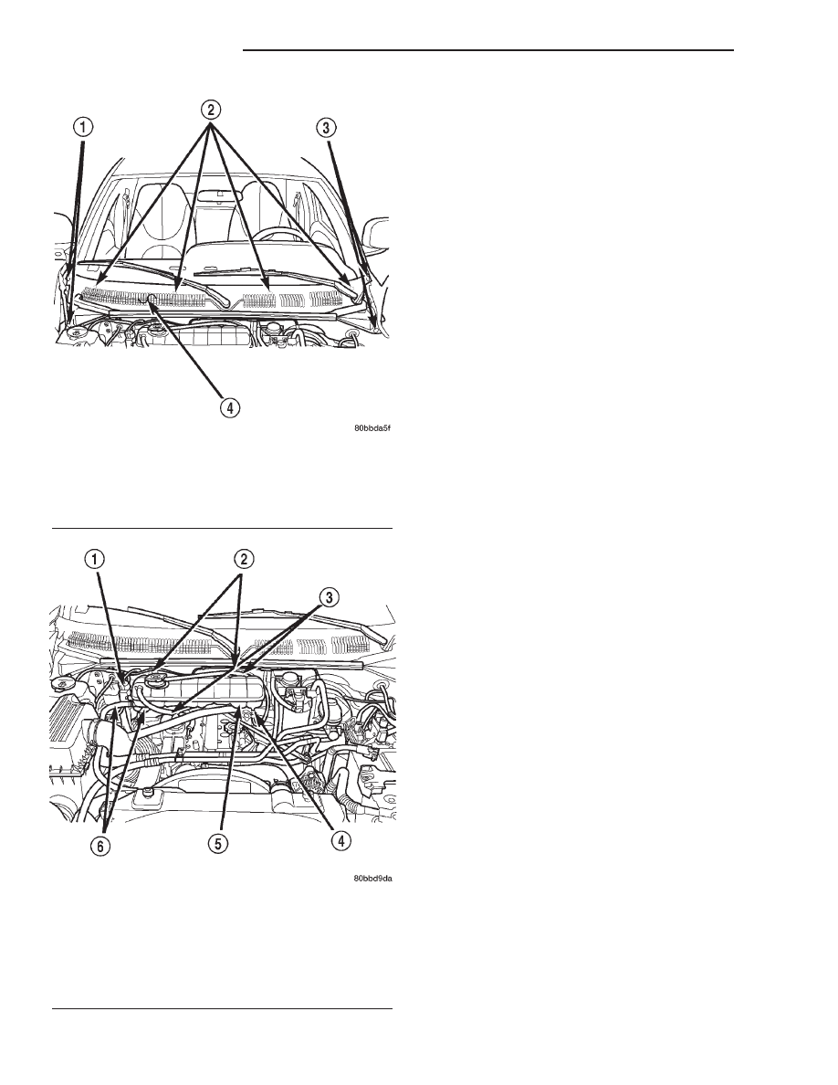
Fig. 22 Cowl Grille

1 - PUSHPINS
2 - COWL GRILLE RETAINING NUTS
3 - PUSHPINS
4 - COWL GRILLE

Fig. 23 Coolant Reservoir Position & Orientation

1 - EGR SOLENOID
2 - COOLANT RESERVOIR RETAINING BOLTS
3 - COOLANT OVERFLOW HOSES
4 - COOLANT LEVEL SENSOR
5 - COOLANT RESERVOIR
6 - COOLANT SUPPLY HOSES

7a - 26

2.5L VM DIESEL

R1

COOLANT TANK (Continued)

5.2L ENGINE

TABLE OF CONTENTS

page

page

5.2L ENGINE

DESCRIPTION . . . . . . . . . . . . . . . . . . . . . . . . . . . 28
OPERATION. . . . . . . . . . . . . . . . . . . . . . . . . . . . . 28
DIAGNOSIS AND TESTING . . . . . . . . . . . . . . . . . 29

DEAERATION . . . . . . . . . . . . . . . . . . . . . . . . . . 29
LEAKS . . . . . . . . . . . . . . . . . . . . . . . . . . . . . . . 29
PRELIMINARY CHECKS. . . . . . . . . . . . . . . . . . 31
ON-BOARD DIAGNOSTICS (OBD) . . . . . . . . . . 37

STANDARD PROCEDURE . . . . . . . . . . . . . . . . . . 37

DRAINING AND FILLING . . . . . . . . . . . . . . . . . 37

CLEANING . . . . . . . . . . . . . . . . . . . . . . . . . . . . . . 38
SPECIFICATIONS . . . . . . . . . . . . . . . . . . . . . . . . 39
SPECIAL TOOLS . . . . . . . . . . . . . . . . . . . . . . . . . 39

BLOCK HEATER

DESCRIPTION . . . . . . . . . . . . . . . . . . . . . . . . . . . 40
OPERATION. . . . . . . . . . . . . . . . . . . . . . . . . . . . . 40
REMOVAL . . . . . . . . . . . . . . . . . . . . . . . . . . . . . . 40
INSTALLATION. . . . . . . . . . . . . . . . . . . . . . . . . . . 40

COOLANT

DESCRIPTION . . . . . . . . . . . . . . . . . . . . . . . . . . . 41
OPERATION. . . . . . . . . . . . . . . . . . . . . . . . . . . . . 41
DIAGNOSIS AND TESTING . . . . . . . . . . . . . . . . . 41

LOW LEVEL AERATION . . . . . . . . . . . . . . . . . . 41

STANDARD PROCEDURE . . . . . . . . . . . . . . . . . . 41

LEVEL CHECK . . . . . . . . . . . . . . . . . . . . . . . . . 41
ROUTINE LEVEL CHECK . . . . . . . . . . . . . . . . . 42

COOLANT SELECTION AND ADDITIVES

DESCRIPTION . . . . . . . . . . . . . . . . . . . . . . . . . . . 42

ELECTRIC COOLING FAN

DIAGNOSIS AND TESTING . . . . . . . . . . . . . . . . . 42

ELECTRIC COOLING FAN . . . . . . . . . . . . . . . . 42

FAN BLADE

CLEANING . . . . . . . . . . . . . . . . . . . . . . . . . . . . . . 43
INSPECTION . . . . . . . . . . . . . . . . . . . . . . . . . . . . 43

HOSE CLAMPS

DESCRIPTION . . . . . . . . . . . . . . . . . . . . . . . . . . . 43
OPERATION. . . . . . . . . . . . . . . . . . . . . . . . . . . . . 43

THERMOSTAT

DESCRIPTION . . . . . . . . . . . . . . . . . . . . . . . . . . . 44
OPERATION. . . . . . . . . . . . . . . . . . . . . . . . . . . . . 44
DIAGNOSIS AND TESTING . . . . . . . . . . . . . . . . . 44

GAS ENGINE . . . . . . . . . . . . . . . . . . . . . . . . . . 44

REMOVAL . . . . . . . . . . . . . . . . . . . . . . . . . . . . . . 44
INSTALLATION. . . . . . . . . . . . . . . . . . . . . . . . . . . 45

RADIATOR

DESCRIPTION . . . . . . . . . . . . . . . . . . . . . . . . . . . 46
OPERATION. . . . . . . . . . . . . . . . . . . . . . . . . . . . . 46
REMOVAL . . . . . . . . . . . . . . . . . . . . . . . . . . . . . . 46
CLEANING . . . . . . . . . . . . . . . . . . . . . . . . . . . . . . 48
INSPECTION . . . . . . . . . . . . . . . . . . . . . . . . . . . . 48
INSTALLATION. . . . . . . . . . . . . . . . . . . . . . . . . . . 49

RADIATOR CAP

DIAGNOSIS AND TESTING . . . . . . . . . . . . . . . . . 49

RADIATOR CAP PRESSURE . . . . . . . . . . . . . . 49

CLEANING . . . . . . . . . . . . . . . . . . . . . . . . . . . . . . 50
INSPECTION . . . . . . . . . . . . . . . . . . . . . . . . . . . . 50

RADIATOR COOLANT FLOW CHECK

DIAGNOSIS AND TESTING . . . . . . . . . . . . . . . . . 50

RADIATOR COOLANT FLOW CHECK. . . . . . . . 50

RADIATOR DRAINCOCK

REMOVAL . . . . . . . . . . . . . . . . . . . . . . . . . . . . . . 50
INSTALLATION. . . . . . . . . . . . . . . . . . . . . . . . . . . 51

RADIATOR PRESSURE CAP

DESCRIPTION . . . . . . . . . . . . . . . . . . . . . . . . . . . 51
OPERATION. . . . . . . . . . . . . . . . . . . . . . . . . . . . . 51

VISCOUS FAN DRIVE

DESCRIPTION . . . . . . . . . . . . . . . . . . . . . . . . . . . 51
OPERATION. . . . . . . . . . . . . . . . . . . . . . . . . . . . . 52
DIAGNOSIS AND TESTING . . . . . . . . . . . . . . . . . 52

VISCOUS FAN DRIVE . . . . . . . . . . . . . . . . . . . 52

REMOVAL . . . . . . . . . . . . . . . . . . . . . . . . . . . . . . 53
INSTALLATION. . . . . . . . . . . . . . . . . . . . . . . . . . . 54

WATER PUMP

DESCRIPTION . . . . . . . . . . . . . . . . . . . . . . . . . . . 54
OPERATION. . . . . . . . . . . . . . . . . . . . . . . . . . . . . 54
REMOVAL . . . . . . . . . . . . . . . . . . . . . . . . . . . . . . 54
CLEANING . . . . . . . . . . . . . . . . . . . . . . . . . . . . . . 56
INSPECTION . . . . . . . . . . . . . . . . . . . . . . . . . . . . 56
INSTALLATION. . . . . . . . . . . . . . . . . . . . . . . . . . . 56

WATER PUMP BYPASS HOSE

DESCRIPTION . . . . . . . . . . . . . . . . . . . . . . . . . . . 56
OPERATION. . . . . . . . . . . . . . . . . . . . . . . . . . . . . 57
REMOVAL . . . . . . . . . . . . . . . . . . . . . . . . . . . . . . 57
INSTALLATION. . . . . . . . . . . . . . . . . . . . . . . . . . . 58

COOLANT RESERVE/OVERFLOW/SYSTEM

DESCRIPTION . . . . . . . . . . . . . . . . . . . . . . . . . . . 59
OPERATION. . . . . . . . . . . . . . . . . . . . . . . . . . . . . 59

R1

5.2L ENGINE

7a - 27

5.2L ENGINE

DESCRIPTION

The cooling system consists of:
• Radiator

• Cooling fan (mechanical/Electrical)

• Thermal viscous fan drive

• Fan shroud

• Radiator pressure cap

• Thermostat

• Coolant reserve/overflow system (integral to

upper fan shroud)

• Transmission oil cooler (if equipped with an

automatic transmission)

• Coolant

• Water pump (Fig. 1)

• Hoses and hose clamps (Fig. 2)

OPERATION

The cooling system regulates engine operating tem-

perature. It allows the engine to reach normal oper-
ating temperature as quickly as possible. It also
maintains normal operating temperature and pre-
vents overheating.

The cooling system also provides a means of heat-

ing the passenger compartment and cooling the auto-
matic transmission fluid (if equipped). The cooling
system is pressurized and uses a centrifugal water
pump to circulate coolant throughout the system.

An optional factory installed maximum duty cool-

ing package is available on most models. This pack-
age will provide additional cooling capacity for
vehicles used under extreme conditions such as
trailer towing in high ambient temperatures.

The cooling system is closed and designed to main-

tain coolant level to top of radiator.

Fig. 1 Engine Cooling System Flow—5.2L/5.9L Engines—Typical

1 - HEATER
2 - BYPASS*

3 - CROSSFLOW RADIATOR

7a - 28

5.2L ENGINE

R1

DIAGNOSIS AND TESTING - DEAERATION

As the engine operates, any air trapped in cooling

system gathers under the radiator cap. The next time
the engine is operated, thermal expansion of coolant
will push any trapped air past radiator cap into the
coolant reserve/overflow tank. Here it escapes to the
atmosphere into the tank. When the engine cools
down the coolant, it will be drawn from the reserve/
overflow tank into the radiator to replace any
removed air.

DIAGNOSIS AND TESTING - LEAKS

ULTRAVIOLET LIGHT METHOD

A leak detection additive is available through the

parts department that can be added to cooling sys-

tem. The additive is highly visible under ultraviolet
light (black light). Pour one ounce of additive into
cooling system. Place heater control unit in HEAT
position. Start and operate engine until radiator
upper hose is warm to touch. Aim the commercially
available black light tool at components to be
checked. If leaks are present, black light will cause
additive to glow a bright green color.

The black light can be used in conjunction with a

pressure tester to determine if any external leaks
exist (Fig. 3).

PRESSURE TESTER METHOD

The engine should be at normal operating tempera-

ture. Recheck the system cold if cause of coolant loss is
not located during the warm engine examination.

Fig. 2 Engine Cooling System Flow—4.7L Engine—Typical

1 - LH CYL. HEAD
2 - BLEED
3 - THERMOSTAT LOCATION
4 - RH CYL. HEAD

5 - RH BANK CYL. BLOCK
6 - LH BANK CYL. BLOCK
7 - COOLANT TEMP. SENSOR

R1

5.2L ENGINE

7a - 29

5.2L ENGINE (Continued)


Content   ..  268  269  270  271   ..