Dodge Dakota (R1). Manual - part 228


  Index      Dodge     Dodge Dakota (R1) - service repair manual 2000 year


Search            


Content   ..  226  227  228  229   ..


Dodge Dakota (R1). Manual - part 228


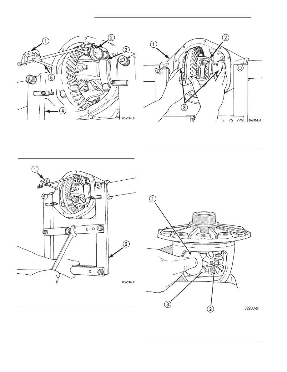
(12) While holding the differential case in position,

remove the differential bearing cap bolts and caps.

(13) Remove differential from the housing and tag

differential bearing cups and shims to indicate loca-
tion (Fig. 36).

(14) Remove spreader from housing.

DISASSEMBLY

(1) Remove pinion shaft lock roll pin with a ham-

mer and punch.

(2) Remove pinion shaft.
(3) Rotate differential side gears and remove the

differential pinions and thrust washers (Fig. 37).

Fig. 34 Dial Indicator Location

1 - INDICATOR CLAMP
2 - DIAL INDICATOR
3 - PLUNGER
4 - SPREADER
5 - PILOT STUD

Fig. 35 Spread Differential Housing

1 - DIAL INDICATOR
2 - SPREADER

Fig. 36 Differential

1 - DIFFERENTIAL HOUSING
2 - DIFFERENTIAL CASE
3 - BEARING CUPS

Fig. 37 Differential Case

1 - THRUST WASHER
2 - SIDE GEAR
3 - DIFFERENTIAL PINION

3a - 22

REAR AXLE - 216RBI

R1

DIFFERENTIAL (Continued)

(4) Remove the differential side gears and thrust

washers.

ASSEMBLY

(1) Install differential side gears and thrust wash-

ers.

(2) Install differential pinion gears and thrust

washers.

(3) Install the pinion mate shaft.
(4) Align the hole in the pinion mate shaft with

the hole in the differential case and install the pinion
mate shaft roll pin.

(5) Lubricate

all

differential

components

with

hypoid gear lubricant.

INSTALLATION

NOTE: If replacement differential bearings or differ-
ential case are being installed, differential side
bearing shim requirements may change. Refer
Adjustments (Differential Bearing Preload and Gear
Backlash) to determine the proper shim selection.

(1) Position

Spreader

W-129-B,

utilizing

some

items from Adapter set 6987, with the tool dowel pins
seated in the locating holes. Install the holddown
clamps and tighten the tool turnbuckle finger-tight.

(2) Install a Pilot Stud C-3288-B at the left side of

the differential housing. Attach Dial Indicator C-3339
to pilot stud. Load the indicator plunger against the
opposite side of the housing and zero the indicator.

CAUTION: Do not spread over 0.50 mm (0.020 in). If
the housing is over–spread, it could be distorted or
damaged.

(3) Spread the housing enough to install the case

in the housing. Measure the distance with the dial
indicator.

(4) Remove the dial indicator.
(5) Install differential case in the housing. Ensure

that the differential bearing cups remain in position
on the differential bearings and that the preload
shims remain between the face of the bearing cup
and the housing. Tap the differential case to ensure
the bearings cups and shims are fully seated in the
housing.

(6) Install the bearing caps in their original loca-

tions (Fig. 38).

(7) Loosely install differential bearing cap bolts.
(8) Remove axle housing spreader.
(9) Tighten the bearing cap bolts to 108 N·m (80 ft.

lbs.).

(10) Install the axle shafts.
(11) Apply a 6.35mm (1/4 in.) bead of Mopar Sili-

cone Rubber Sealant or equivalent to the housing
cover (Fig. 39).

CAUTION: If the cover is not installed within 3-5
minutes the cover must be cleaned and new RTV
must be applied.

(12) Install the cover and any identification tag.

Tighten the cover bolts in a criss-cross pattern to 41
N·m (30 ft. lbs.).

Fig. 38 Bearing Cap Reference

1 - REFERENCE LETTER
2 - REFERENCE LETTER

Fig. 39 Typical Differential Cover

1 - COVER
2 - SEALANT SURFACE
3 - SEALANT

R1

REAR AXLE - 216RBI

3a - 23

DIFFERENTIAL (Continued)

(13) Refill the differential with Mopar Hypoid

Gear Lubricant or equivalent to bottom of the fill
plug hole.

(14) Install the fill hole plug.
(15) Remove support and lower the vehicle.

DIFFERENTIAL - TRAC-LOK

DIAGNOSIS AND TESTING - TRAC-LOK

T

The most common problem is a chatter noise when

turning corners. Before removing the unit for repair,
drain, flush and refill the axle with the specified
lubricant. A container of Mopar Trac-lok

t Lubricant

(friction modifier) should be added after repair ser-
vice or during a lubricant change.

After changing the lubricant, drive the vehicle and

make 10 to 12 slow, figure-eight turns. This maneu-
ver will pump lubricant through the clutches. This
will correct the condition in most instances. If the
chatter persists, clutch damage could have occurred.

DIFFERENTIAL TEST

The differential can be tested without removing the

differential case by measuring rotating torque. Make
sure brakes are not dragging during this measure-
ment.

(1) Place blocks in front and rear of both front

wheels.

(2) Raise one rear wheel until it is completely off

the ground.

(3) Engine off, transmission in neutral, and park-

ing brake off.

(4) Remove wheel and bolt Special Tool 6790 or

equivalent tool to studs.

(5) Use torque wrench on special tool to rotate

wheel and read rotating torque (Fig. 40).

(6) If rotating torque is less than 22 N·m (30 ft.

lbs.) or more than 271 N·m (200 ft. lbs.) on either
wheel the unit should be serviced.

DISASSEMBLY

(1) Clamp side gear Holding Fixture 6965 in a vise

and position the differential case on the Holding Fix-
ture (Fig. 41).

(2) Remove ring gear if the ring gear is to be

replaced. The Trac-lok™ differential can be serviced
with the ring gear installed.

Fig. 40 Rotating Torque - Typical

1 - SPECIAL TOOL
2 - TORQUE WRENCH

Fig. 41 Differential Case Holding Fixture

1 - HOLDING FIXTURE
2 - VISE
3 - DIFFERENTIAL

3a - 24

REAR AXLE - 216RBI

R1

DIFFERENTIAL (Continued)

(3) Remove the pinion gear mate shaft lock screw

(Fig. 42).

(4) Remove pinion gear mate shaft with a drift and

hammer (Fig. 43).

(5) Install and lubricate Step Plate C-6960-3 (Fig.

44).

(6) Assemble Threaded Adapter C-4487-3 into top

side gear. Thread Forcing Screw C-4487-2 into
adapter until it becomes centered in adapter plate.

(7) Position

a

small

screw

driver

in

slot

of

Threaded Adapter Disc C-4487-3 (Fig. 45) to prevent
adapter from turning.

Fig. 42 Mate Shaft Lock Screw

1 - LOCK SCREW
2 - PINION GEAR MATE SHAFT

Fig. 43 Mate Shaft

1 - PINION MATE SHAFT
2 - SIDE GEAR
3 - DRIFT
4 - PINION MATE GEAR

Fig. 44 Step Plate

1 - LOWER SIDE GEAR
2 - DIFFERENTIAL CASE
3 - STEP PLATE

Fig. 45 Threaded Adapter Disc

1 - SOCKET
2 - SLOT IN ADAPTER
3 - SCREWDRIVER
4 - STEP PLATE
5 - THREADED ROD
6 - THREADED ADAPTER DISC

R1

REAR AXLE - 216RBI

3a - 25

DIFFERENTIAL - TRAC-LOK (Continued)


Content   ..  226  227  228  229   ..