Dodge Dakota (R1). Manual - part 226
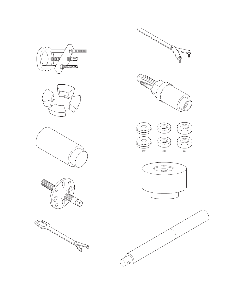
SPECIAL TOOLS
REAR AXLE
Puller C-293-PA
Adapter C-293-39
Adapter Plug SP-3289
Puller C-452
Wrench C-3281
Wrench Spanner 6958
Installer C-3718
Dummy Bearings 6776
Gauge Block 8144
Handle C-4171
3a - 14
REAR AXLE - 216RBI
R1
REAR AXLE - 216RBI (Continued)