Dodge Dakota (R1). Manual - part 227


  Index      Dodge     Dodge Dakota (R1) - service repair manual 2000 year


Search            


Content   ..  225  226  227  228   ..


Dodge Dakota (R1). Manual - part 227


PINION SEAL

REMOVAL

(1) Raise and support the vehicle.
(2) Remove wheel and tire assemblies.
(3) Remove brake drums, refer to 5 Brakes for pro-

cedures.

(4) Mark propeller shaft and pinion yoke for

installation reference.

(5) Remove the propeller shaft from the yoke.
(6) Rotate pinion gear three or four times and ver-

ify that pinion rotates smoothly.

(7) Record torque necessary to rotate the pinion

gear with a inch pound dial-type torque wrench.

(8) Using Spanner Wrench 6958 to hold the pinion

yoke, remove the pinion nut and washer.

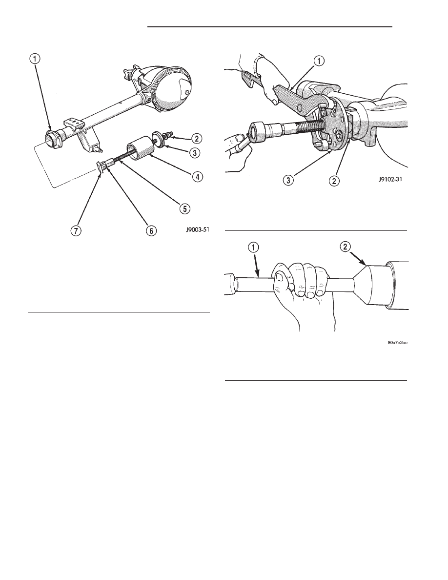
(9) Remove the pinion yoke with Remover C-452

and Wrench C-3281 (Fig. 23).

(10) Remove pinion shaft seal with a pry tool or

slide hammer mounted screw.

INSTALLATION

(1) Apply a light coating of gear lubricant on the

lip of pinion seal. Install seal with an appropriate
installer (Fig. 24).

(2) Install yoke on pinion gear with Installer

W-162-D, Cup 8109 and Wrench 6958 (Fig. 25).

CAUTION: Do not exceed the minimum tightening
torque 217 N·m (160 ft. lbs.) when installing the pin-
ion yoke retaining nut at this point. Damage to the
pinion bearings may result.

(3) Install pinion washer and a new nut on the

pinion gear and tighten the nut until there is zero
bearing end-play.

(4) Tighten pinion nut to 217 N·m (160 ft. lbs.).
(5) Rotate pinion gear a minimum of ten times and

verify pinion rotates smoothly. Rotate pinion shaft an
inch pound torque wrench. Rotating torque should be
equal to recorded reading plus an additional 0.56
N·m (5 in. lbs.) (Fig. 26).

Fig. 22 Axle Shaft Bearing Tools

1 - AXLE SHAFT TUBE
2 - NUT
3 - GUIDE PLATE
4 - GUIDE
5 - THREADED ROD
6 - ADAPTER
7 - FOOT

Fig. 23 Pinion Yoke Removal

1 - WRENCH
2 - YOKE
3 - REMOVER

Fig. 24 Pinion Seal

1 - HANDLE
2 - INSTALLER

3a - 18

REAR AXLE - 216RBI

R1

PINION SEAL (Continued)

(6) If the rotating torque is low, use Spanner

Wrench 6958 to hold the pinion yoke, and tighten the
pinion nut in 6.8 N·m (5 ft. lbs.) increments until the
proper rotating torque is achieved.

(7) Install propeller shaft with reference marks

aligned.

(8) Add gear lubricant to the differential if neces-

sary.

(9) Install the brake drums, refer to 5 Brakes for

procedures.

(10) Install wheel and tire assemblies.
(11) Lower the vehicle.

COLLAPSIBLE SPACER

REMOVAL

(1) Raise and support the vehicle.
(2) Remove wheel and tire assemblies.
(3) Remove rear brake drums.
(4) Mark propeller shaft and pinion yoke for

installation reference.

(5) Remove propeller shaft from the yoke.
(6) Rotate pinion gear three or four times.
(7) Record torque necessary to rotate the pinion

gear with an inch pound dial-type torque wrench.

(8) Hold pinion yoke with Spanner Wrench 6958

and remove pinion nut and washer.

(9) Remove pinion yoke with Remover C-452 and

Flange Wrench C-3281 (Fig. 27).

(10) Remove pinion shaft seal with a pry tool or a

slide hammer mounted screw.

(11) Remove front pinion bearing using a pair of

pick tools to pull the bearing straight off the pinion
gear shaft.

NOTE: If bearing becomes bound on pinion shaft,
lightly tap the pinion shaft with a rawhide/rubber
hammer.

(12) Remove the collapsible spacer.

Fig. 25 Pinion Yoke Installation

1 - INSTALLER
2 - YOKE
3 - DIFFEREFTIAL HOUSING
4 - WRENCH

Fig. 26 Pinion Rotating Torque

1 - TORQUE WRENCH
2 - PINION YOKE

Fig. 27 Pinion Yoke

1 - FLANGE WRENCH
2 - YOKE
3 - REMOVER

R1

REAR AXLE - 216RBI

3a - 19

PINION SEAL (Continued)

INSTALLATION

(1) Install a new collapsible preload spacer on pin-

ion shaft.

(2) Install pinion front bearing.
(3) Apply a light coating of gear lubricant on the

lip of pinion seal and install seal with an appropriate
installer (Fig. 28).

(4) Install yoke with Installer C-3718 and Spanner

Wrench 6958 (Fig. 29).

(5) Install yoke washer and new nut on the pinion

gear. Tighten the nut to 298 N·m (220 ft. lbs.).

CAUTION: Never loosen pinion gear nut to decrease
pinion rotating torque and never exceed specified
preload torque. If preload torque or rotating torque
is exceeded a new collapsible spacer must be
installed.

(6) Using Spanner Wrench 6958 and a torque

wrench set at 380 N·m (280 ft. lbs.), (Fig. 30) slowly
tighten the nut in 6.8 N·m (5 ft. lbs.) increments
until the rotating torque is achieved. Measure the
rotating torque frequently to avoid over crushing the
collapsible spacer (Fig. 31).

NOTE: If more than 380 N·m (280 ft. lbs.) torque is
required to crush the collapsible spacer, the spacer
is defective and must be replaced.

(7) Check rotating torque with an inch pound

torque wrench (Fig. 31). The rotating torque of the
pinion gear should be, the reading recorded during
removal plus an additional 0.56 N·m (5 in. lbs.).

(8) Install propeller shaft with reference marks

aligned.

(9) Install rear brake drums.
(10) Add gear lubricant, if necessary.
(11) Install wheel and tire assemblies.
(12) Remove supports and lower vehicle.

Fig. 28 Pinion Seal

1 - HANDLE
2 - INSTALLER

Fig. 29 Pinion Yoke Installation

1 - INSTALLER
2 - PINION YOKE
3 - DIFFERENTIAL HOUSING
4 - SPANNER WRENCH

Fig. 30 Tightening Pinion Nut

1 - HOLDER
2 - PIPE
3 - TORQUE WRENCH

3a - 20

REAR AXLE - 216RBI

R1

COLLAPSIBLE SPACER (Continued)

DIFFERENTIAL

REMOVAL

(1) Raise and support vehicle.
(2) Remove fill hole plug from the differential

housing cover.

(3) Remove differential housing cover and drain

fluid.

(4) Clean the housing cavity with flushing oil, light

engine oil or lint free cloth.

NOTE: Do not use water, steam, kerosene or gaso-
line for cleaning.

(5) Remove axle shafts.
(6) Note the reference letters stamped on the bear-

ing caps and housing machined sealing surface (Fig.
32).

(7) Loosen the differential bearing cap bolts.
(8) Position Spreader W-129-B with Adapter Kit

6987B on differential locating holes (Fig. 33). Install
the holddown clamps and tighten the tool turnbuckle
finger-tight.

(9) Install a Pilot Stud C-3288-B at the left side of

the differential housing. Attach Dial Indicator C-3339
to pilot stud. Load the indicator plunger against the
opposite side of the housing (Fig. 34) and zero the
indicator.

CAUTION: Never spread the housing over 0.51 mm
(0.020 in). If housing is over-spread, it could dis-
torted and damaged the housing.

(10) Spread housing enough to remove the differ-

ential case from the housing. Measure the distance
with the dial indicator (Fig. 35).

(11) Remove the dial indicator.

Fig. 31 Pinion Rotating Torque

1 - TORQUE WRENCH
2 - PINION YOKE

Fig. 32 Bearing Cap Identification

1 - REFERENCE LETTER
2 - REFERENCE LETTER

Fig. 33 Spreader Location

1 - DIFFERENTIAL HOUSING
2 - ADAPTER
3 - CLAMP
4 - TURNBUCKLE

R1

REAR AXLE - 216RBI

3a - 21

COLLAPSIBLE SPACER (Continued)


Content   ..  225  226  227  228   ..