Dodge Dakota (R1). Manual - part 229


  Index      Dodge     Dodge Dakota (R1) - service repair manual 2000 year


Search            


Content   ..  227  228  229  230   ..


Dodge Dakota (R1). Manual - part 229


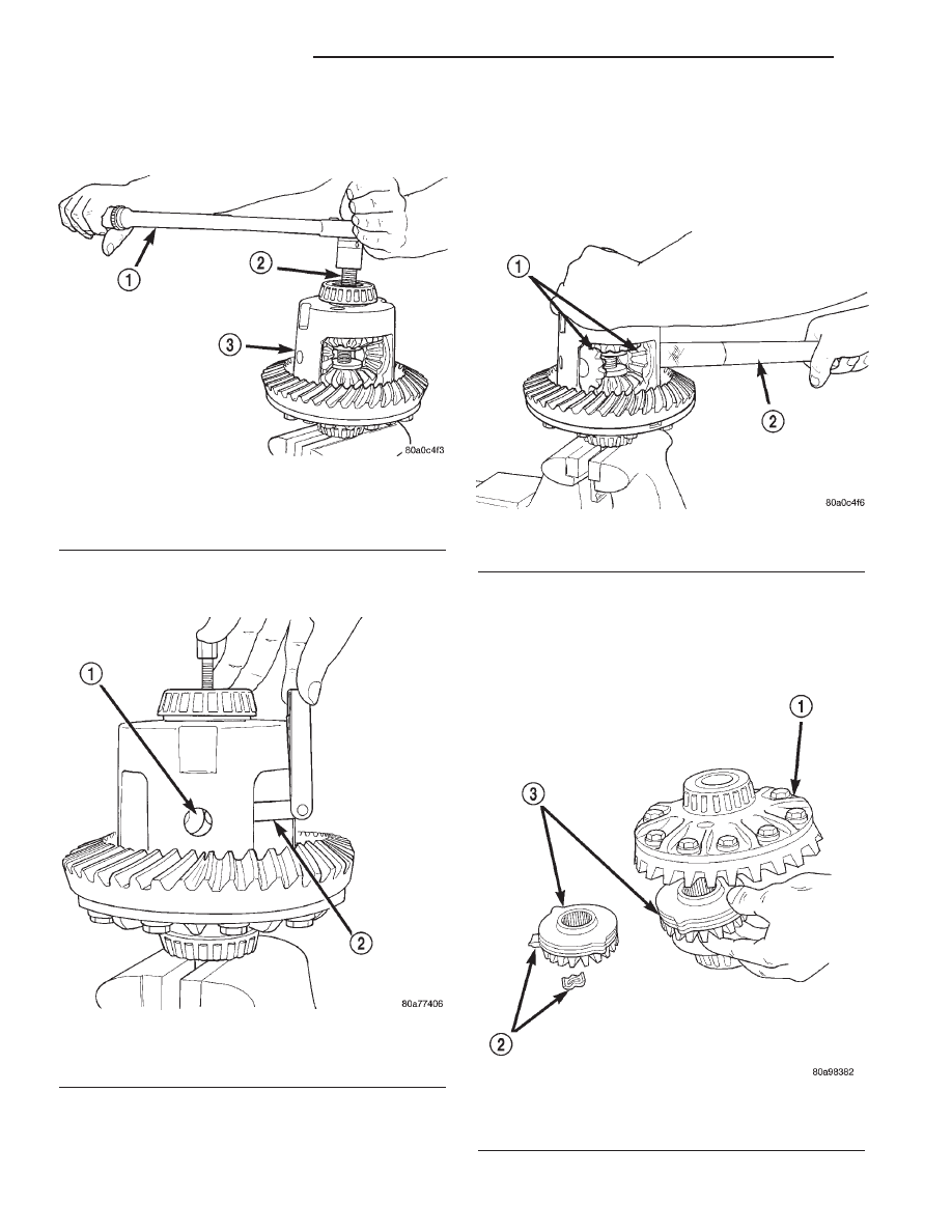
(8) Install Forcing Screw and tighten screw to 122

N·m (90 ft. lbs.) maximum to compress Belleville
springs in clutch packs (Fig. 46).

(9) With a feeler gauge remove thrust washers

from behind the pinion gears (Fig. 47).

(10) Insert Turning Bar C-4487-4 into the pinion

mate shaft hole in the case (Fig. 48).

(11) Loosen the Forcing Screw in small increments

until the clutch pack tension is relieved and the dif-
ferential case can be turned using Turning Bar.

(12) Rotate differential case until the pinion gears

can be removed.

(13) Remove pinion gears from differential case.

(14) Remove

Forcing

Screw,

Step

Plate

and

Threaded Adapter.

(15) Remove top side gear, clutch pack retainer

and clutch pack. Keep plates in correct order during
removal (Fig. 49).

Fig. 46 Compress Belleville Spring

1 - TORQUE WRENCH
2 - FORCING SCREW
3 - DIFFERENTIAL CASE

Fig. 47 Pinion Gear Thrust Washer

1 - THRUST WASHER
2 - FEELER GAUGE

Fig. 48 Differential Pinion Gear

1 - PINION GEARS
2 - TURNING BAR

Fig. 49 Side Gear & Clutch Pack

1 - DIFFERENTIAL CASE
2 - RETAINER
3 - SIDE GEAR AND CLUTCH PACK

3a - 26

REAR AXLE - 216RBI

R1

DIFFERENTIAL - TRAC-LOK (Continued)

(16) Remove differential case from the Holding Fix-

ture. Remove side gear, clutch pack retainer and clutch
pack. Keep plates in correct order during removal.

ASSEMBLY

Lubricate each component with gear lubricant

before assembly.

(1) Assemble the clutch discs into packs and

secure disc packs with retaining clips (Fig. 50).

NOTE: New Plates and discs with fiber coating (no
grooves or lines) must be presoaked in Friction
Modifier before assembly. Soak plates and discs for
a minimum of 20 minutes.

(2) Position assembled clutch disc packs on the

side gear hubs.

(3) Install clutch pack and side gear in the ring

gear side of the differential case (Fig. 51). Be sure
clutch pack retaining clips remain in position
and are seated in the case pockets.

(4) Position the differential case on the Holding

Fixture 6963-A.

(5) Install lubricated Step Plate C-4487-1 in lower

side gear (Fig. 52).

(6) Install the upper side gear and clutch disc pack

(Fig. 52).

(7) Hold assembly in position. Insert Threaded

Adapter C-4487-3 into top side gear.

(8) Install Forcing Screw C-4487-2 and tighten

screw to slightly compress clutch disc.

(9) Place pinion gears in position in side gears and

verify that the pinion mate shaft hole is aligned.

(10) Rotate case with Turning Bar C-4487-4 until

the pinion mate shaft holes in pinion gears align
with holes in case. It may be necessary to slightly
tighten the forcing screw in order to install the pin-
ion gears.

Fig. 50 Clutch Disc Pack

1 - CLUTCH PACK
2 - RETAINER
3 - SIDE GEAR
4 - RETAINER

Fig. 51 Clutch Pack & Lower Side Gear

1 - DIFFERENTIAL CASE
2 - LOWER SIDE GEAR AND CLUTCH PACK

Fig. 52 Clutch Pack & Upper Side Gear

1 - UPPER SIDE GEAR AND CLUTCH PACK
2 - DIFFERENTIAL CASE
3 - STEP PLATE

R1

REAR AXLE - 216RBI

3a - 27

DIFFERENTIAL - TRAC-LOK (Continued)

(11) Tighten forcing screw to 122 N·m (90 ft. lbs.)

maximum to compress the Belleville springs.

(12) Lubricate and install thrust washers behind

pinion gears and align washers with a small screw
driver. Insert mate shaft into each pinion gear to ver-
ify alignment.

(13) Remove

Forcing

Screw,

Step

Plate

and

Threaded Adapter.

(14) Install pinion gear mate shaft and align holes

in shaft and case.

(15) Install pinion mate shaft lock screw finger

tight to hold shaft during differential installation.

(16) Lubricate all differential components with

hypoid gear lubricant.

DIFFERENTIAL CASE BEARINGS

REMOVAL

(1) Remove differential case from axle housing.
(2) Remove differential bearings from the case

with Puller C-293-PA and Adapters C-293-42 and
Plug C-293-3 (Fig. 53).

INSTALLATION

(1) Install differential side bearings with Installer

C-4340 and Handle C-4171 (Fig. 54).

(2) Install differential case into housing.

PINION GEAR/RING GEAR

REMOVAL

NOTE: The ring and pinion gears are serviced in a
matched set. Never replace one gear without replac-
ing the other gear.

(1) Raise and support the vehicle.
(2) Mark pinion yoke and propeller shaft for

installation alignment.

(3) Disconnect propeller shaft from pinion yoke.

Tie propeller shaft to underbody.

(4) Remove differential from axle housing.
(5) Place differential case in a vise with soft metal

jaw.

(6) Remove ring gear bolts from the differential

case.

(7) Drive ring gear from the differential case with

a rawhide hammer (Fig. 55).

(8) Hold pinion yoke with Wrench 6958 and

remove pinion yoke nut and washer.

Fig. 53 Differential Bearing Puller

1 - PULLER
2 - ADAPTERS
3 - BEARING
4 - DIFFERENTIAL
5 - PLUG

Fig. 54 Differential Bearing Installer

1 - HANDLE
2 - DIFFERENTIAL
3 - BEARING
4 - INSTALLER

3a - 28

REAR AXLE - 216RBI

R1

DIFFERENTIAL - TRAC-LOK (Continued)

(9) Remove pinion yoke from pinion shaft with

Remover C-452 and Wrench C-3281 (Fig. 56).

(10) Remove the pinion gear from housing (Fig.

57).

(11) Remove pinion shaft seal with a pry tool or a

slide hammer mounted screw.

(12) Remove oil slinger, if equipped, and front pin-

ion bearing.

(13) Remove

front

pinion

bearing

cup

with

Remover D-103 and Handle C-4171 (Fig. 58).

Fig. 55 Ring Gear

1 - DIFFERENTIAL CASE
2 - RING GEAR
3 - HAMMER

Fig. 56 Pinion Yoke

1 - FLANGE WRENCH
2 - YOKE
3 - REMOVER

Fig. 57 Pinion Gear

1 - RAWHIDE HAMMER

Fig. 58 Front Pinion Bearing Cup

1 - REMOVER
2 - HANDLE

R1

REAR AXLE - 216RBI

3a - 29

PINION GEAR/RING GEAR (Continued)


Content   ..  227  228  229  230   ..