Dodge Dakota (R1). Manual - part 221


  Index      Dodge     Dodge Dakota (R1) - service repair manual 2000 year


Search            


Content   ..  219  220  221  222   ..


Dodge Dakota (R1). Manual - part 221


(14) Remove

Forcing

Screw,

Step

Plate

and

Threaded Adapter.

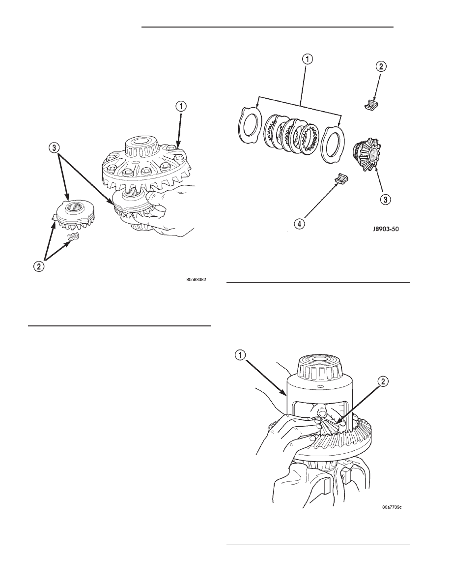
(15) Remove top side gear, clutch pack retainer

and clutch pack. Keep plates in correct order during
removal (Fig. 40).

(16) Remove differential case from the Holding

Fixture. Remove side gear, clutch pack retainer and
clutch pack. Keep plates in correct order during
removal.

ASSEMBLY

Clean all components in cleaning solvent. Dry com-

ponents with compressed air. Inspect clutch pack
plates for wear, scoring or damage. Replace both
clutch packs if any one component in either pack is
damaged. Inspect side gears and pinions. Replace
any gear that is worn, cracked, chipped or damaged.
Inspect differential case and pinion shaft. Replace if
worn or damaged.

Lubricate each component with gear lubricant

before assembly.

(1) Assemble the clutch discs into packs and

secure disc packs with retaining clips (Fig. 41).

NOTE: New Plates and discs with fiber coating (no
grooves or lines) must be presoaked in Friction
Modifier before assembly. Soak plates and discs for
a minimum of 20 minutes.

(2) Position assembled clutch disc packs on the

side gear hubs.

(3) Install clutch pack and side gear in the ring

gear side of the differential case (Fig. 42). Be sure
clutch pack retaining clips remain in position
and are seated in the case pockets.

Fig. 40 Side Gear & Clutch Pack

1 - DIFFERENTIAL CASE
2 - RETAINER
3 - SIDE GEAR AND CLUTCH PACK

Fig. 41 Clutch Disc Pack

1 - CLUTCH PACK
2 - RETAINER
3 - SIDE GEAR
4 - RETAINER

Fig. 42 Clutch Pack & Lower Side Gear

1 - DIFFERENTIAL CASE
2 - LOWER SIDE GEAR AND CLUTCH PACK

3 - 102

REAR AXLE - 9 1/4

AN

DIFFERENTIAL - TRAC-LOK (Continued)

(4) Position the differential case on the Holding

Fixture 6965.

(5) Install lubricated Step Plate C-6960-3 in lower

side gear (Fig. 43).

(6) Install the upper side gear and clutch disc pack

(Fig. 43).

(7) Hold assembly in position. Insert Threaded

Adapter C-6960-1 into top side gear.

(8) Install Forcing Screw C-6960-4 and tighten

screw to slightly compress clutch disc.

(9) Place pinion gears in position in side gears and

verify that the pinion mate shaft hole is aligned.

(10) Rotate case with Turning Bar C-6960-2 until

the pinion mate shaft holes in pinion gears align
with holes in case. It may be necessary to slightly
tighten the forcing screw in order to install the pin-
ion gears.

(11) Tighten forcing screw to 122 N·m (90 ft. lbs.)

maximum to compress the Belleville springs.

(12) Lubricate and install thrust washers behind

pinion gears and align washers with a small screw
driver. Insert mate shaft into each pinion gear to ver-
ify alignment.

(13) Remove

Forcing

Screw,

Step

Plate

and

Threaded Adapter.

(14) Install pinion gear mate shaft and align holes

in shaft and case.

(15) Install pinion mate shaft lock screw finger

tight to hold shaft during differential installation.

(16) Lubricate all differential components with

hypoid gear lubricant.

DIFFERENTIAL CASE
BEARINGS

REMOVAL

(1) Remove differential case from axle housing.
(2) Remove differential bearings from the case

with Puller/Press C-293-PA and Adapters C-293-47
and Plug C-293-3 (Fig. 44).

INSTALLATION

(1) Install differential side bearings with Installer

C-4213 and Handle C-4171 (Fig. 45).

(2) Install differential case into housing.

Fig. 43 Clutch Pack & Upper Side Gear

1 - UPPER SIDE GEAR AND CLUTCH PACK
2 - DIFFERENTIAL CASE
3 - STEP PLATE

Fig. 44 Differential Bearing Puller

1 - PULLER
2 - ADAPTERS
3 - BEARING
4 - DIFFERENTIAL
5 - PLUG

AN

REAR AXLE - 9 1/4

3 - 103

DIFFERENTIAL - TRAC-LOK (Continued)

PINION GEAR/RING GEAR/
TONE RING

REMOVAL

NOTE: The ring gear and pinion are serviced in a
matched set. Never replace one gear without replac-
ing the other.

(1) Raise and support vehicle.
(2) Remove wheel and tire assemblies.
(3) Mark companion flange and propeller shaft for

installation reference.

(4) Disconnect propeller shaft from the companion

flange and tie propeller shaft to underbody.

(5) Remove axle shafts.
(6) Remove differential from the differential hous-

ing.

(7) Place differential case in a vise with soft metal

jaw protectors. (Fig. 46).

(8) Remove ring gear bolts from the differential

case.

(9) Drive ring gear off the differential case with a

rawhide hammer (Fig. 46).

(10) Install bolts into two of the threaded holes in

the companion flange 180° apart.

(11) Position Holder 6719 against the companion

flange and install a bolt and washer into one of the
remaining threaded holes. Tighten the bolts so the
Holder 6719 is held to the flange.

(12) Use Holder 6719 to hold companion flange

and remove the companion flange nut and washer.

(13) Remove the companion flange from the pinion

with Remover C-452 (Fig. 47).

(14) Remove the pinion from housing (Fig. 48).

Fig. 45 Differential Bearing Installer

1 - HANDLE
2 - DIFFERENTIAL
3 - BEARING
4 - INSTALLER

Fig. 46 Ring Gear

1 - CASE
2 - RING GEAR
3 - RAWHIDE HAMMER

Fig. 47 Companion Flange

1 - COMPANION FLANGE
2 - REMOVER

3 - 104

REAR AXLE - 9 1/4

AN

DIFFERENTIAL CASE BEARINGS (Continued)

(15) Remove pinion seal with a pry tool or slide-

hammer mounted screw.

(16) Remove oil slinger if equipped and front pin-

ion bearing.

(17) Remove

front

pinion

bearing

cup

with

Remover C-4345 and Handle C–4171 (Fig. 49).

(18) Remove the rear bearing cup from housing

(Fig. 50) with Remover C-4307 and Handle C–4171.

(19) Remove the collapsible preload spacer (Fig.

51).

(20) Remove rear bearing from the pinion (Fig. 52)

with Puller/Press C-293-PA and Adapters C-293-47.

(21) Remove depth shims from the pinion shaft

and record shim thickness.

INSTALLATION

NOTE: The ring gear and pinion are serviced in a
matched set. Do not replace the pinion without
replacing the ring gear. If ring and pinion gears or
bearings are replaced, Refer to Adjustments for Pin-
ion Gear Depth Setting.

(1) Apply Mopar Door Ease or stick lubricant to

outside surface of bearing cup.

(2) Install rear pinion bearing cup (Fig. 53) with

Installer C-4308 and Driver Handle C-4171 and ver-
ify cup is seated.

(3) Apply Mopar Door Ease or stick lubricant to

outside surface of bearing cup.

(4) Install front pinion bearing cup (Fig. 54) with

Installer D-130 and Handle C-4171 and verify cup is
seated.

(5) Install front pinion bearing.

Fig. 48 Pinion Gear

1 - RAWHIDE HAMMER

Fig. 49 Front Pinion Bearing Cup

1 - REMOVER
2 - HANDLE

Fig. 50 Rear Pinion Bearing Cup

1 - DRIVER
2 - HANDLE

AN

REAR AXLE - 9 1/4

3 - 105

PINION GEAR/RING GEAR/TONE RING (Continued)


Content   ..  219  220  221  222   ..