Dodge Dakota (R1). Manual - part 219
AXLE BEARINGS
REMOVAL
(1) Remove axle shaft.
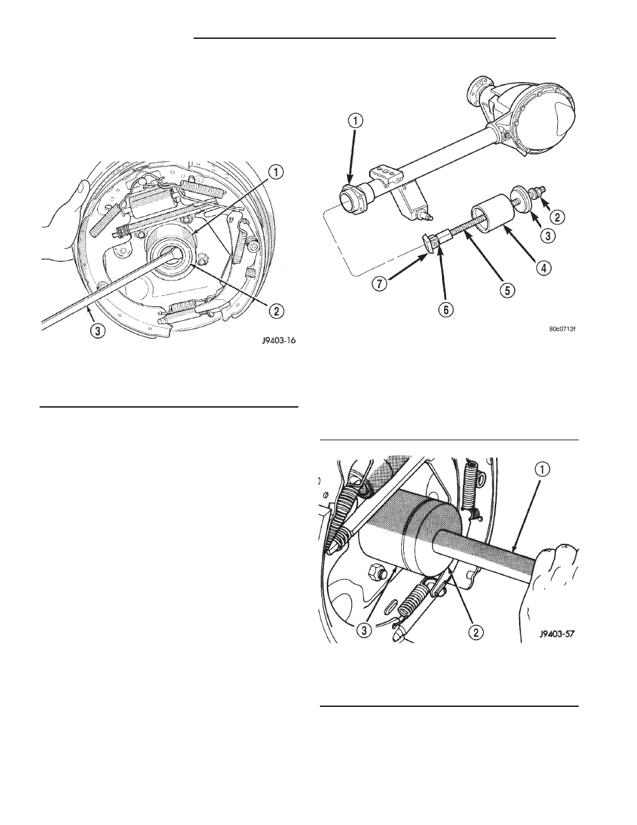
(2) Remove axle shaft seal from the end of the axle
tube with a small pry bar (Fig. 16).
NOTE: The seal and bearing can be removed at the
same time with the bearing removal tool.
(3) Remove the axle shaft bearing from the axle
tube with Bearing Removal Tool Set 6310, using
Adapter Foot 6310-9 (Fig. 17).
INSTALLATION
(1) Wipe the axle tube bore clean. Remove any old
sealer or burrs from the tube.
(2) Install the axle shaft bearing with Installer
C-4198 and Handle C-4171 (Fig. 18). Install the bear-
ing with the bearing part number against the
installer. Verify the bearing in installed straight and
the tool fully contacts the axle tube when seating the
bearing.
(3) Install a new axle seal with Installer C-4076-B
and Handle C-4735-1. When the tool contacts the
axle tube, the seal is installed to the correct depth.
(4) Coat the lip of the seal with axle lubricant for
protection prior to installing the axle shaft.
(5) Install the axle shaft.
Fig. 16 Axle Seal
1 - AXLE TUBE
2 - AXLE SEAL
3 - PRY BAR
Fig. 17 Axle Shaft Bearing Tool
1 - AXLE SHAFT TUBE
2 - NUT
3 - GUIDE PLATE
4 - GUIDE
5 - THREADED ROD
6 - ADAPTER
7 - FOOT
Fig. 18 Seal and Bearing Installer
1 - HANDLE
2 - INSTALLER
3 - AXLE TUBE
3 - 94
REAR AXLE - 9 1/4
AN