Dodge Dakota (R1). Manual - part 218
SPECIFICATIONS
REAR AXLE - 9 1/4
AXLE SPECIFICATIONS
DESCRIPTION
SPECIFICATION
Axle Ratio
3.21, 3.55, 3.92
Differential Case Flange Runout
0.076 mm (0.003 in.)
Differential Case Clearance
0.12 mm (0.005 in.)
Ring Gear Diameter
235 mm (9.25 in.)
Ring Gear Backlash
0.12-0.20 mm (0.005-0.008 in.)
Ring Gear Runout
0.12 mm (0.005 in.)
Pinion Bearing Preload - Original Bearings
1-2 N·m (10-20 in. lbs.)
Pinion Bearing Preload - New Bearings
1.7-4 N·m (15-35 in. lbs.)
TORQUE SPECIFICATIONS
DESCRIPTION
N·m
Ft. Lbs.
In. Lbs.
Differential Cover Bolts
41
30
-
Bearing Cap Bolts
136
100
-
Ring Gear Bolts
157
115
-
Pinion Nut Minimum
285
210
-
Adjuster Lock Screw
10
7.5
90
Backing Plate Bolts
65
48
-
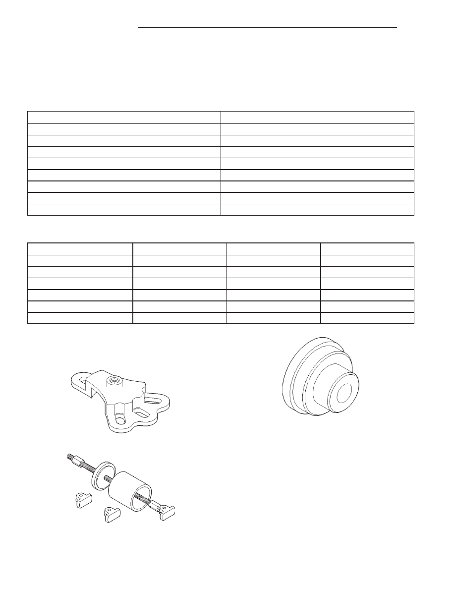
SPECIAL TOOLS
SPECIAL TOOLS
Puller, Hub 6790
Remover 6310
Installer C-4198
3 - 90
REAR AXLE - 9 1/4
AN