Dodge Dakota (R1). Manual - part 217


  Index      Dodge     Dodge Dakota (R1) - service repair manual 2000 year


Search            


Content   ..  215  216  217  218   ..


Dodge Dakota (R1). Manual - part 217


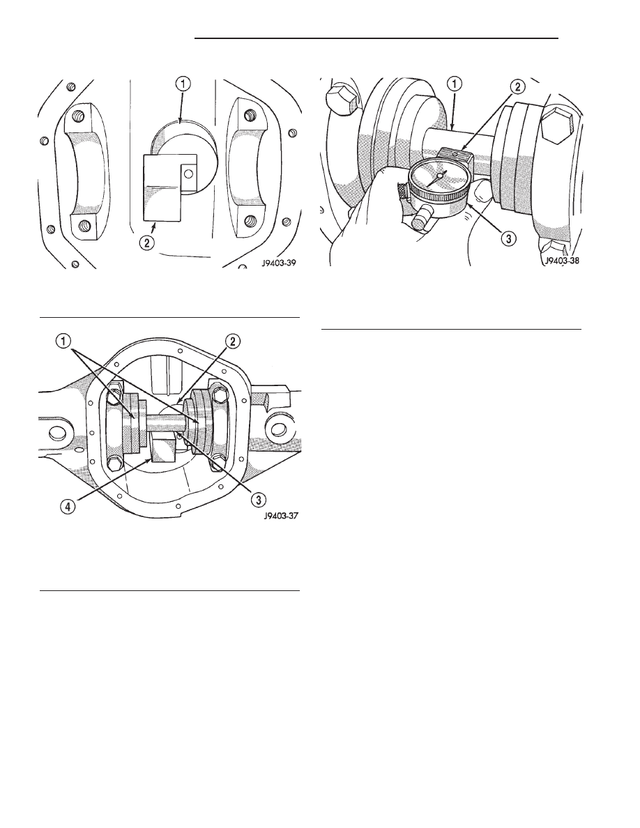
(8) Slide the dial indicator probe across the gap

between the pinion height block and the arbor bar
with the scooter block against the pinion height block
(Fig. 8). When the dial probe contacts the arbor bar,
the dial pointer will turn clockwise. Continue moving
the dial probe to the crest of the arbor bar and record
the highest reading. If the dial indicator can not
achieve the zero reading, the rear bearing cup or the
pinion depth gauge set is not installed correctly.

(9) Select a shim equal to the dial indicator read-

ing plus the drive pinion gear depth variance number
marked on the shaft of the pinion. For example, if
the depth variance is –2, add +0.002 in. to the dial
indicator reading.

DIFFERENTIAL BEARING PRELOAD AND GEAR
BACKLASH

The following must be considered when adjusting

bearing preload and gear backlash:

• The maximum ring gear backlash variation is

0.003 inch (0.076 mm).

• Mark the gears so the same teeth are meshed

during all backlash measurements.

• Maintain the torque while adjusting the bearing

preload and ring gear backlash.

• Excessive adjuster torque will introduce a high

bearing load and cause premature bearing failure.
Insufficient adjuster torque can result in excessive
differential case free-play and ring gear noise.

• Insufficient adjuster torque will not support the

ring gear correctly and can cause excessive differen-
tial case free-play and ring gear noise.

NOTE: The differential bearing cups will not always
immediately follow the threaded adjusters as they
are moved during adjustment. To ensure accurate
bearing cup responses to the adjustments:

• Maintain the gear teeth engaged (meshed) as

marked.

• The bearings must be seated by rapidly rotating

the pinion gear a half turn back and forth.

• Do this five to ten times each time the threaded

adjusters are adjusted.

(1) Use Wrench C-4164 to adjust each threaded

adjuster inward until the differential bearing free-
play is eliminated (Fig. 9). Allow some ring gear
backlash

(approximately

0.25

mm

/

0.01

inch)

between the ring and pinion gear. Seat the bearing
cups with the procedure described above.

Fig. 6 Pinion Height Block

1 - PINION BLOCK
2 - PINION HEIGHT BLOCK

Fig. 7 Pinion Depth Tools

1 - ARBOR DISC
2 - PINION BLOCK
3 - ARBOR
4 - PINION HEIGHT BLOCK

Fig. 8 Pinion Gear Depth Measurement

1 - ARBOR
2 - SCOOTER BLOCK
3 - DIAL INDICATOR

3 - 86

REAR AXLE - 9 1/4

AN

REAR AXLE - 9 1/4 (Continued)

(2) Install dial indicator and position the plunger

against the drive side of a ring gear tooth (Fig. 10).
Measure the backlash at 4 positions (90 degrees
apart) around the ring gear. Locate and mark the
area of minimum backlash.

(3) Rotate the ring gear to the position of the least

backlash. Mark the gear so that all future backlash
measurements will be taken with the same gear
teeth meshed.

(4) Loosen the right-side, tighten the left-side

threaded adjuster. Obtain backlash of 0.003 to 0.004
inch (0.076 to 0.102 mm) with each adjuster tight-

ened to 14 N·m (10 ft. lbs.). Seat the bearing cups
with the procedure described above.

(5) Tighten the differential bearing cap bolts 136

N·m (100 ft. lbs.).

(6) Tighten the right-side threaded adjuster to 102

N·m (75 ft. lbs.). Seat the bearing cups with the pro-
cedure described above. Continue to tighten the
right-side adjuster and seat bearing cups until the
torque remains constant at 102 N·m (75 ft. lbs.)

(7) Measure the ring gear backlash. The range of

backlash is 0.006 to 0.008 inch (0.15 to 0.203 mm).

(8) Continue increasing the torque at the right-

side threaded adjuster until the specified backlash is
obtained.

NOTE:

The

left-side

threaded

adjuster

torque

should have approximately 102 N·m (75 ft. lbs.). If
the torque is considerably less, the complete
adjustment procedure must be repeated.

(9) Tighten the left-side threaded adjuster until

102 N·m (75 ft. lbs.) torque is indicated. Seat the
bearing rollers with the procedure described above.
Do this until the torque remains constant.

(10) Install

the

threaded

adjuster

locks

and

tighten the lock screws to 10 N·m (90 in. lbs.).

After the proper backlash is achieved, perform the

Gear Contact procedure.

GEAR CONTACT PATTERN

The ring gear and pinion teeth contact patterns

will show if the pinion depth is correct in the hous-
ing. It will also show if the ring gear backlash has
been adjusted correctly. The backlash can be adjusted
within specifications to achieve desired tooth contact
patterns.

(1) Apply a thin coat of hydrated ferric oxide or

equivalent to the drive and coast side of the ring gear
teeth.

(2) Wrap, twist, and hold a shop towel around the

pinion yoke to increase the turning resistance of the
pinion. This will provide a more distinct contact pat-
tern.

(3) With a boxed end wrench on a ring gear bolt,

rotate the differential case one complete revolution in
both directions while a load is being applied from
shop towel.

The areas on the ring gear teeth with the greatest

degree of contact against the pinion teeth will squee-
gee the compound to the areas with the least amount
of contact. Note and compare patterns on the ring
gear teeth to Gear Tooth Contact Patterns chart (Fig.
11)and adjust pinion depth and gear backlash as nec-
essary.

Fig. 9 Threaded Adjuster Tool

1 - AXLE TUBE
2 - BACKING PLATE
3 - THREAD ADJUSTER WRENCH

Fig. 10 Ring Gear Backlash

1 - DIAL INDICATOR
2 - RING GEAR
3 - EXCITER RING

AN

REAR AXLE - 9 1/4

3 - 87

REAR AXLE - 9 1/4 (Continued)

Fig. 11 Gear Tooth Contact Patterns

3 - 88

REAR AXLE - 9 1/4

AN

REAR AXLE - 9 1/4 (Continued)

SIDE GEAR CLEARANCE

When measuring side gear clearance, check each

gear independently. If it necessary to replace a side
gear, replace both gears as a matched set.

(1) Install the axle shafts and C-locks and pinion

mate shaft.

(2) Measure each side gear clearance. Insert a

matched pair of feeler gauge blades between the gear
and differential housing on opposite sides of the hub
(Fig. 12) .

(3) If side gear clearances is no more than 0.005

inch. Determine if the axle shaft is contacting the
pinion mate shaft. Do not remove the feeler
gauges, inspect the axle shaft with the feeler
gauge inserted behind the side gear. 
If the end of
the axle shaft is not contacting the pinion mate
shaft, the side gear clearance is acceptable.

(4) If clearance is more than 0.005 inch (axle shaft

not contacting mate shaft), record the side gear clear-
ance. Remove the thrust washer and measure its
thickness with a micrometer. Add the washer thick-
ness to the recorded side gear clearance. The sum of
gear clearance and washer thickness will determine
required thickness of replacement thrust washer
(Fig. 13). In some cases, the end of the axle shaft will

move and contact the mate shaft when the feeler
gauge is inserted. The C-lock is preventing the side
gear from sliding on the axle shaft.

(5) If there is no side gear clearance, remove the

C-lock from the axle shaft. Use a micrometer to mea-
sure the thrust washer thickness. Record the thick-
ness and re-install the thrust washer. Assemble the
differential case without the C-lock installed and re-
measure the side gear clearance.

(6) Compare both clearance measurements. If the

difference is less than 0.012 inch (0.305 mm), add
clearance recorded when the C-lock was installed to
thrust washer thickness measured. The sum will
determine the required thickness of the replacement
thrust washer.

(7) If clearance is 0.012 inch (0.305 mm) or

greater, both side gears must be replaced (matched
set) and the clearance measurements repeated.

(8) If clearance (above) continues to be 0.012 inch

(0.305 mm) or greater, the case must be replaced.

Fig. 12 Side Gear Clearance

1 - FEELER GAUGE
2 - SIDE GEAR

Fig. 13 Side Gear Calculations

AN

REAR AXLE - 9 1/4

3 - 89

REAR AXLE - 9 1/4 (Continued)


Content   ..  215  216  217  218   ..