DAF LF45, LF55 Series. Manual - part 535


  Index      DAF     DAF LF45, LF55 Series - service repair manual


Search            


Content   ..  533  534  535  536   ..


DAF LF45, LF55 Series. Manual - part 535


7

LF45/55 series

Removal and installation

FRONT AXLE, F60

3-5

3.3 REMOVAL AND INSTALLATION OF TRACK ROD
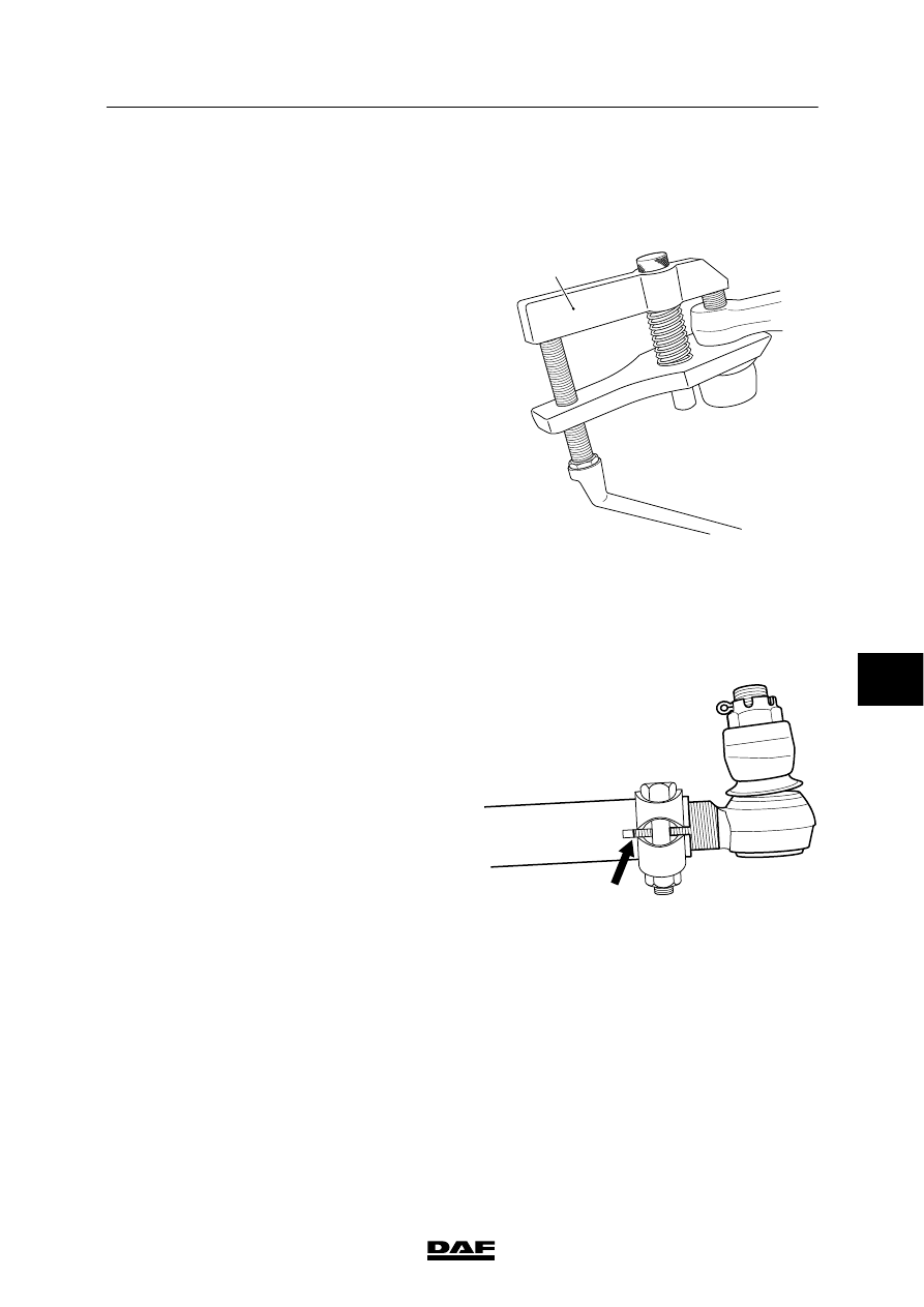
Removing track rod
1.

Remove the castle nuts.

2.

Take the ball ends out of the track-rod arms
using a ball-end puller (A).

Installing track rod
1.

When installing a new track rod, copy the
settings of the track rod to be replaced.

2.

Clean the tapered contact surfaces of both
the track rod balls and the track rod arms.
The tapered surfaces must be absolutely
free of dirt, grease and paint.

3.

Fit the track rod.

4.

Fit the castle nuts and tighten them to the
specified torque, see “Technical data”.

Note:
If the split-pin hole in the ball end does not
match the recesses in the castle nut, tighten
the castle nut further.

5.

Lock the castle nuts using new split pins.

6.

Check the axle toe and adjust if necessary.
See “Inspection and adjustment”.

S7 00 555

A

7.

Check that the threaded end of the ball joint
is fully secured by the clamping piece.

8.

Check that the clamping piece bolt is
tightened to the specified tightening torque,
see “Technical data”.

S7 00 026

7

ᓻ 200322

7

FRONT AXLE, F60

Removal and installation

LF45/55 series

3-6

3.4 REMOVAL AND INSTALLATION OF TRACK-ROD ARM

These instructions must be
followed to the letter. The
attachment of the track-rod arms is
one of the most critical factors in
terms of vehicle safety. Always use
new attachment bolts when fitting
the track-rod arm. Always use
original attachment bolts of the
prescribed length supplied by DAF.

Removing track-rod arm
1.

Take the track rod off the track-rod arm.

2.

Remove the attachment bolts.

Note:
These bolts must not be reused.

3.

Take the track-rod arm off the swivel axle.

Installing track-rod arm
1.

Clean and check the screw thread in the
swivel axle. The screw thread must not be
damaged.

2.

Clean and degrease the contact surfaces of
the swivel axle and the arm.

3.

Apply the specified locking compound to the
new attachment bolts, see “Technical data”.

4.

Use new attachment bolts when installing
the track-rod arm.
Evenly tighten the attachment bolts
alternately to the specified tightening
torque, see “Technical data”.

5.

Fit the track rod.

7

ᓻ 200322

7

LF45/55 series

Removal and installation

FRONT AXLE, F60

3-7

3.5 REMOVAL AND INSTALLATION OF STEERING-ROD ARM

These instructions must be
followed to the letter. The
attachment of the steering-rod arm
is one of the most critical factors in
terms of vehicle safety. Always use
new attachment bolts when
installing the steering-rod arm.
Always use original attachment
bolts of the prescribed length
supplied by DAF.

Removing steering-rod arm
1.

Take the steering rod out of the steering-rod
arm.

2.

Remove the attachment bolts.

Note:
These bolts must not be reused.

3.

Take the steering-rod arm off the swivel
axle.

Installing steering-rod arm
1.

Clean and check the screw thread in the
swivel axle. The screw thread must not be
damaged.

2.

Clean and degrease the contact surfaces of
the swivel axle and the arm.

3.

Apply the specified locking compound to the
new attachment bolts, see “Technical data”.

4.

Use new attachment bolts when installing
the steering-rod arm. Evenly tighten the
attachment bolts alternately to the specified
tightening torque, see “Technical data”.

5.

Install the steering rod.

7

ᓻ 200322

7

FRONT AXLE, F60

Removal and installation

LF45/55 series

3-8

3.6 REMOVAL AND INSTALLATION OF WHEEL HUB

Removing wheel hub
1.

Jack up the axle until the wheels are clear
of the floor. Place suitable supports under
the axle.

2.

Remove the wheel.

3.

Take the attachment bolts (1) off the wheel
hub (2) and remove the wheel hub (2).

Installing wheel hub
1.

Check that the contact surfaces of the
wheel hub (2) and the brake disc (3) are
clean. Clean these if necessary.

2.

Install the wheel hub (2) and tighten the
attachment bolts (1) crosswise to the
specified tightening torque, see “Technical
data”.

3.

Fit the wheel.

2

3

S7 00 802

7

ᓻ 200322


Content   ..  533  534  535  536   ..