Chrysler Pacifica. Manual - part 453
fluid level is above tips of bleeder tubes in reservoir
to ensure no air is ingested during bleeding.
(4) Using a wooden dowel as a pushrod (Fig. 47),
slowly depress master cylinder pistons, then release
pressure, allowing pistons to return to released posi-
tion. Repeat several times until all air bubbles are
expelled. Make sure fluid level stays above tips of
bleeder tubes in reservoir while bleeding.
(5) Remove bleeder tubes from master cylinder
outlet ports, then plug outlet ports and install fill cap
on reservoir.
(6) Remove master cylinder from vise.
(7) Install master cylinder on vehicle. (Refer to 5 -
BRAKES - BASE/HYDRAULIC/MECHANICAL/MAS-
TER CYLINDER - INSTALLATION)
REMOVAL
CAUTION: Vacuum in power brake booster must be
pumped down (removed) before removing master
cylinder from power brake booster. This is neces-
sary to prevent power brake booster from sucking
in
any
contamination
as
master
cylinder
is
removed. This can be done simply by pumping
brake pedal, with vehicle’s engine not running, until
a firm feeling brake pedal is achieved.
(1) With engine not running, pump brake pedal
until a firm pedal is achieved (4-5 strokes).
(2) Disconnect negative battery cable from battery
post and isolate.
(3) Thoroughly clean all surfaces of brake fluid
reservoir and master cylinder. Use only Mopar
t
Brake Parts Cleaner or equivalent.
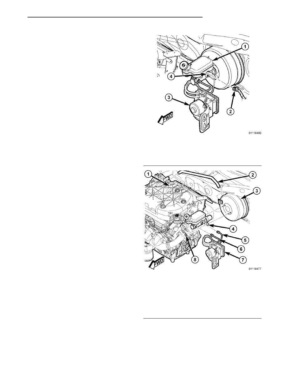
(4) Disconnect
wiring
harness
connector
from
brake fluid level switch in master cylinder brake
fluid reservoir (Fig. 48).
(5) Disconnect primary and secondary brake tubes
from master cylinder (Fig. 49). Install sealing plugs
in open brake tube outlet ports.
CAUTION: Before removing master cylinder from
power brake vacuum booster, master cylinder and
vacuum booster must be thoroughly cleaned. This
must be done to prevent dirt particles from falling
into power brake vacuum booster.
(6) Clean area where master cylinder assembly
attaches to power brake booster. Use only Mopar
t
Brake Parts Cleaner or equivalent.
(7) Remove two nuts attaching master cylinder to
power brake booster (Fig. 49).
(8) Slide master cylinder straight out of power
brake booster.
CAUTION: Seal on rear of master cylinder is used
to create seal for holding vacuum in power brake
vacuum booster. Vacuum seal on master cylinder
MUST be replaced whenever master cylinder is
removed from power brake vacuum booster.
(9) Remove vacuum seal located on mounting
flange of master cylinder. Vacuum seal is removed
Fig. 48 Brake Fluid Level Switch Connector
1 - MASTER CYLINDER RESERVOIR
2 - WIRING CONNECTOR
3 - ABS ICU
4 - BRAKE FLUID LEVEL SWITCH
Fig. 49 Master Cylinder Mounting
1 - ENGINE INTAKE MANIFOLD
2 - BOOSTER VACUUM HOSE
3 - POWER BRAKE BOOSTER
4 - MASTER CYLINDER
5 - PRIMARY BRAKE TUBE
6 - SECONDARY BRAKE TUBE
7 - ABS ICU
8 - MASTER CYLINDER MOUNTING NUT (2)
CS
BRAKES - BASE
5 - 27
MASTER CYLINDER (Continued)