Chrysler Pacifica. Manual - part 452
CAUTION: Use care when installing caliper onto
disc brake adapter to avoid damaging boots on cal-
iper guide pins.
(5) Retract caliper guide pins to clear mounting
bosses on caliper adapter when installing caliper.
(6) Install brake caliper in opposite way it was
removed. Starting with upper end, carefully position
caliper and brake shoes over brake rotor and align
outboard shoe’s upper edge with caliper slide abut-
ment. Rotate lower end of caliper into mounting posi-
tion on adapter.
CAUTION: Extreme caution should be taken not to
crossthread caliper guide pin bolts when they are
installed.
(7) Carefully install caliper guide pin bolts (Fig.
24). Tighten bolts to 23 N·m (200 in. lbs.) torque.
(8) Install banjo bolt attaching brake hose to cali-
per (Fig. 24). Install NEW washers on each side of
hose fitting as banjo bolt is placed through fitting.
Thread banjo bolt into caliper and tighten to 47 N·m
(35 ft. lbs.) torque.
(9) Install tire and wheel assembly. Tighten wheel
mounting nuts to 135 N·m (100 ft. lbs.) torque. (Refer
to 22 - TIRES/WHEELS - INSTALLATION)
(10) Lower vehicle.
(11) Remove brake pedal holding tool.
(12) Connect battery negative cable to battery
post.
(13) Bleed base brake hydraulic system as neces-
sary. (Refer to 5 - BRAKES - STANDARD PROCE-
DURE)
(14) Road test vehicle making several stops to
wear off any foreign material on brakes and to seat
brake shoes.
DISC BRAKE CALIPER
ADAPTER - FRONT
REMOVAL
(1) Access and remove front brake caliper and
shoes. (Refer to 5 - BRAKES/HYDRAULIC/ME-
CHANICAL/BRAKE PADS/SHOES - REMOVAL)
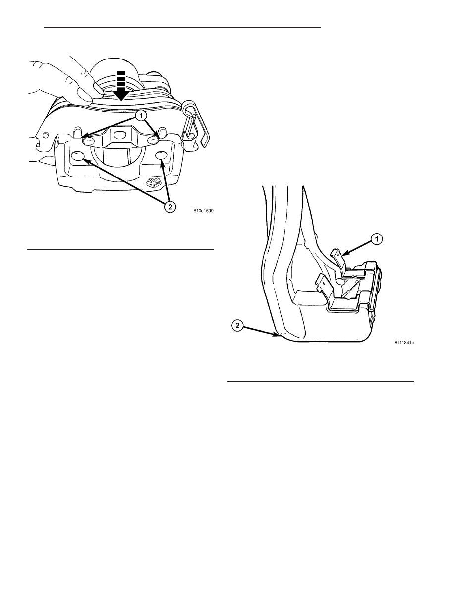
(2) Remove shoe anti-rattle clips from adapter
(Fig. 41).
(3) Remove two bolts securing caliper adapter to
steering knuckle (Fig. 42).
(4) Remove caliper adapter.
INSTALLATION
NOTE: Brake caliper adapters are side-oriented. Left
adapters are marked with an “L” while right adapt-
ers are marked with an “R” where shown (Fig. 43).
(1) Install disc brake caliper adapter on steering
knuckle.
(2) Install two bolts securing caliper adapter to
steering knuckle (Fig. 42). Tighten bolts to 169 N·m
(125 ft. lbs.) torque.
(3) Attach two brake shoe anti-rattle clips to
adapter matching contour of each clip to adapter’s
upper and lower caliper abutments (Fig. 41).
Fig. 40 Outboard Shoe Installation
1 - LOCATING PINS POSITIONED AGAINST RAMPS
2 - HOLES
Fig. 41 Anti-Rattle Clip - Lower (Upper - Typical)
1 - ANTI-RATTLE CLIP
2 - CALIPER ADAPTER
CS
BRAKES - BASE
5 - 23
DISC BRAKE CALIPER - REAR (Continued)