Chery Tiggo 5 (T21). Manual - part 426


  Index      Chery     Chery Tiggo 5 (T21) - service repair manual 2014 year


Search            


Content   ..  424  425  426  427   ..


Chery Tiggo 5 (T21). Manual - part 426


37–

44

37

Front Door Key Cylinder

Removal

1. Turn off all the electrical equipment and ignition switch.
2. Disconnect the negative battery cable.
3. Remove the front left door protector assembly (

See page 47-23

).

4. Remove the front left door assist grip mounting bracket assembly (

See page 47-29

).

5. Remove the front left door protective film assembly (

See page 47-30

).

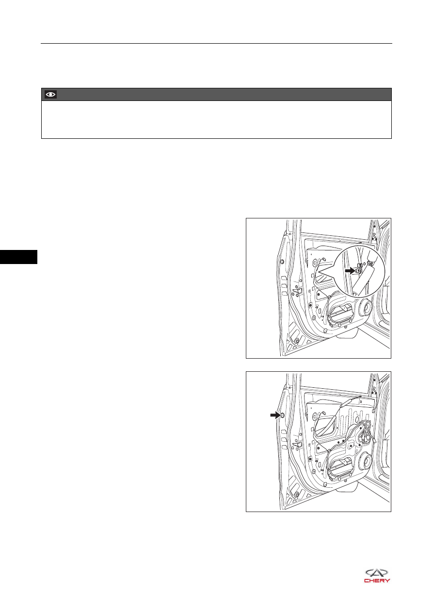
6. Remove the front left door key cylinder protective cover.

a. Disconnect the clip (arrow) between front door lock 

assembly and front door lock key cylinder lever.

b. Using a screwdriver wrapped with protective tape, 

remove the trim plug (arrow) of front door key cylinder 
protective cover.

c. Remove the fixing screw from front door key cylinder protective cover, and remove the front left door 

key cylinder protective cover.

(Tightening torque: 5 ± 1 N·m)

CAUTION

 Be sure to the wear safety equipment to prevent accidents when removing front door key cylinder.
 Try to prevent interior and body paint from being scratched when removing front door key cylinder.

RT21370080

RT21370120

37–

45

37

HINT:
It is not necessary to remove the fixing screw from front left door key cylinder protective cover, because 
the fixing screw is integrated with the front door key cylinder protective cover.

7. Remove the front left door key cylinder.

a. Detach the clip (arrow) from front door key cylinder 

lever. 

b. Using a screwdriver wrapped with protective tape, 

disengage the claws (arrow) to separate the front door 
key cylinder protective cover from front door key 
cylinder.

Installation

Installation is in the reverse order of removal.

RT21370130

RT21370140

CAUTION

 Install clip on the lever in place when installing front door key cylinder.
 Check if front door key cylinder operates properly after installing front door key cylinder.

37–

46

37

Front Door Lock Striker Assembly

Removal

HINT:

 Use the same procedures for the right side and left side.

 Procedures listed below are for the left side.

1. Remove the front left door lock striker assembly.

a. Remove 2 fixing crews (arrow) from front left door lock 

striker assembly.

(Tightening torque: 10 ± 1 N·m)

b. Remove the front left door lock striker assembly.

Installation

Installation is in the reverse order of removal.

CAUTION

 Be sure to the wear safety equipment to prevent accidents when removing front door lock striker 

assembly.

 Try to prevent body paint surface from being scratched when removing front door lock striker assembly.

RT21370150

CAUTION

 Try to prevent body paint surface from being scratched when installing front door lock striker assembly.

37–

47

37

Rear Door Lock Assembly

Removal

HINT:

 Use the same procedures for the right side and left side.

 Procedures listed below are for the left side.

1. Turn off all the electrical equipment and ignition switch.
2. Disconnect the negative battery cable.
3. Remove the rear left door protector assembly (

See page 47-36

).

4. Remove the rear left door assist grip mounting bracket assembly (

See page 47-41

).

5. Remove the rear left door protective film assembly (

See page 47-41

).

6. Remove the rear left door lock assembly.

a. Disconnect the connector (arrow) from rear door lock 

assembly. 

b. Detach the cable (arrow) connecting rear door lock 

assembly and rear door assist grip base.

CAUTION

 Be sure to the wear safety equipment to prevent accidents when removing rear door lock assembly.
 Try to prevent interior and body paint from being scratched when removing rear door lock assembly.

RT21370170

RT21370180


Content   ..  424  425  426  427   ..