Chery Tiggo 5 (T21). Manual - part 425


  Index      Chery     Chery Tiggo 5 (T21) - service repair manual 2014 year


Search            


Content   ..  423  424  425  426   ..


Chery Tiggo 5 (T21). Manual - part 425


37–

39

37

ON-VEHICLE SERVICE

Engine Hood Lock Assembly

Removal

1. Turn off all the electrical equipment and ignition switch.
2. Disconnect the negative battery cable.
3. Remove the radiator grille assembly (

See page 48-8

).

4. Remove the water tank upper crossmember trim board (

See page 48-10

). 

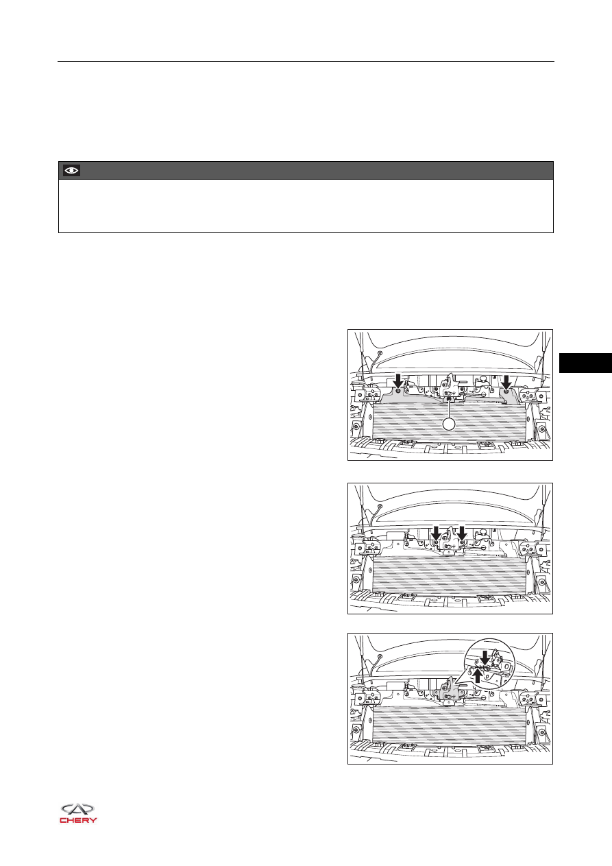
5. Remove the tank upper crossmember deflector. 

a. Remove 2 plastic clips (arrow) and the fixing nut (1) 

from tank upper crossmember deflector.

(Tightening torque: 10 ± 1 N·m)

b. Remove the tank upper crossmember deflector. 

6. Remove the engine hood lock assembly.

a. Remove 2 fixing nuts (arrow) from engine hood lock 

assembly.

(Tightening torque: 10 ± 1 N·m)

b. Detach the engine hood cable assembly (arrow) from 

clamping part, and remove the engine hood lock 
assembly.

CAUTION

 Be sure to the wear safety equipment to prevent accidents when removing engine hood lock assembly.
 Try to prevent body paint surface from being scratched when removing engine hood lock assembly.

1

RT21370050

RT21370060

RT21370061

37–

41

37

Front Door Lock Assembly

Removal

HINT:

 Use the same procedures for the right side and left side.

 Procedures listed below are for the left side.

1. Turn off all the electrical equipment and ignition switch.
2. Disconnect the negative battery cable.
3. Remove the front left door protector assembly (

See page 47-36

).

4. Remove the front left door assist grip mounting bracket assembly (

See page 47-41

).

5. Remove the front left door protective film assembly (

See page 47-41

).

6. Remove the front left door glass rear guide rail assembly (

See page 43-51

).

7. Remove the front left door lock assembly.

a. Disconnect the connector (arrow) from front door lock 

assembly. 

b. Detach the clip (arrow) connecting front door lock 

assembly and front door key cylinder lever.

CAUTION

 Be sure to the wear safety equipment to prevent accidents when removing front door lock assembly.
 Try to prevent interior and body paint from being scratched when removing front door lock assembly.

RT21370070

RT21370080

37–

42

37

c. Detach the cable (arrow) connecting front door lock 

assembly and front door assist grip base.

d. Remove 3 fixing screws (arrow) from front door lock 

assembly, and remove the front door lock assembly.

(Tightening torque: 5.8 ± 0.7 N·m)

Inspection

1. Check front door lock assembly (fastener assembly).

a. Apply battery voltage to terminals of front door lock assembly (fastener assembly) connector and check 

if front door lock assembly works properly according to the table below.
Front Left Door Lock Assembly

RT21370090

RT21370100

RT21370110

-

+

1 2 3 4 5 6

Measurement Condition

Specified 

Condition

Battery positive (+) → Terminal 3

Battery negative (-) → Terminal 2

Lock

Battery positive (+) → Terminal 2

Battery negative (-) → Terminal 3

Unlock

37–

43

37

Front Right Door Lock Assembly

If result is not as specified, replace front door lock 
assembly.

Installation

Installation is in the reverse order of removal.

Measurement Condition

Specified 

Condition

Battery positive (+) → Terminal 4

Battery negative (-) → Terminal 5

Lock

Battery positive (+) → Terminal 5

Battery negative (-) → Terminal 4

Unlock

CAUTION

 Check if connector is installed correctly when installing front door lock assembly.
 Install clip and cable on the lever in place when installing front door lock assembly.
 Check if front door lock operates properly after installing front door lock assembly.


Content   ..  423  424  425  426   ..