Chery Tiggo 5 (T21). Manual - part 424


  Index      Chery     Chery Tiggo 5 (T21) - service repair manual 2014 year


Search            


Content   ..  422  423  424  425   ..


Chery Tiggo 5 (T21). Manual - part 424


37–

35

37

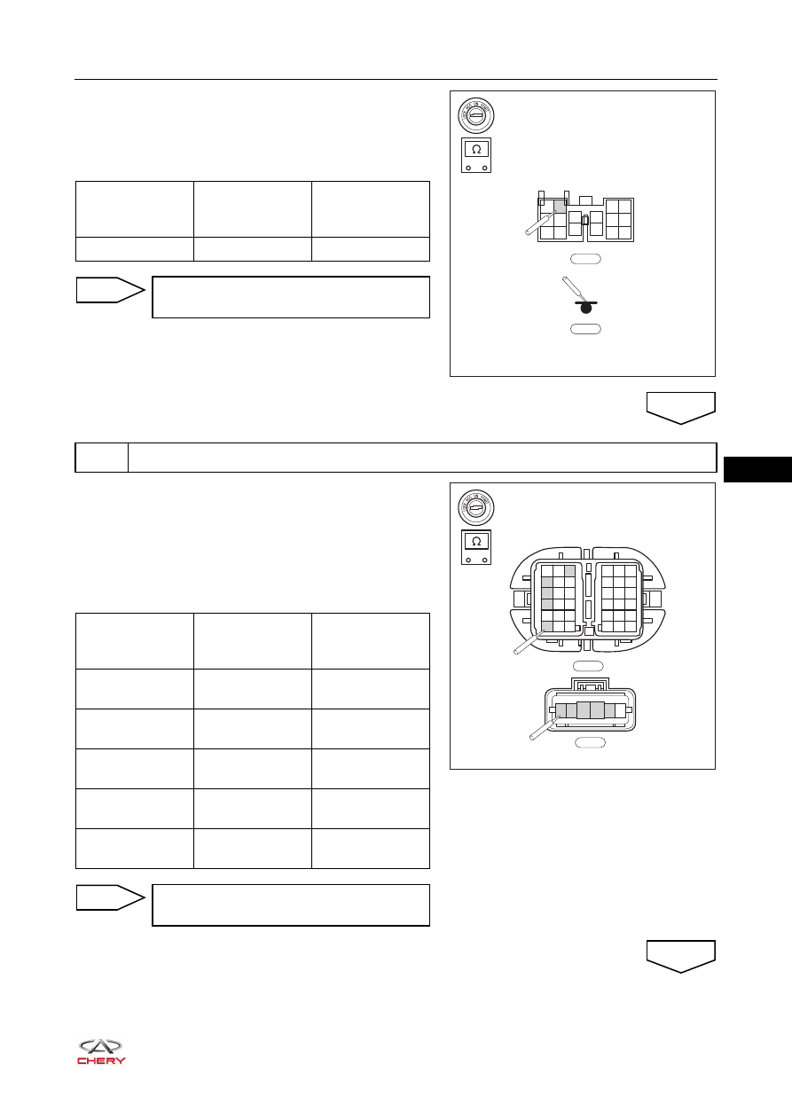
ae.Disconnect the body wire harness connector B-005 and 

ground B-062.

af. Using a digital multimeter, check for continuity between 

body wire harness connector B-005 and B-062 according 
to the table below.

a. Turn ignition switch to LOCK.
b. Disconnect the negative battery cable.
c. Disconnect the front left door wire harness connectors 

F-007 and F-002.

d. Using a digital multimeter, check for continuity between 

front left door wire harness connectors F-007 and F-002 
according to the table below.

-

+

RT21370640

1

2

7

8

13

14

3

4

9

10

5

6

11

12

15

16

B-005

B-062

Multimeter 

Connection 

Terminal

Condition

Specified 

Condition

B-005 (5) - B-062

Always

Continuity

Repair or replace body wire harness and 
connector

NG

4

Check front left door wire harness and connector

OK

-

+

RT21370650

1

1

2

2

3

3

4 5 6

7 8 9

10 11 12

13 14 15

16

4

7

10

13

16

17

5

8

11

14

17

18

6

9

12

15

18

F-007

1

2

3

4

5

6

F-002

Multimeter 

Connection 

Terminal

Condition

Specified 

Condition

F-007 (4) - F-002 

(2) 

Always

Continuity

F-007 (7) - F-002 

(3) 

Always

Continuity

F-007 (10) - F-002 

(4) 

Always

Continuity

F-007 (3) - F-002 

(5) 

Always

Continuity

F-007 (16) - F-002 

(6) 

Always

Continuity

Repair or replace front left door wire 
harness and connector

NG

OK

37–

36

37

a. Turn ignition switch to LOCK.
b. Disconnect the negative battery cable.
c. Disconnect the front right door wire harness connectors 

H-002 and H-005.

d. Using a digital multimeter, check for continuity between 

front right door wire harness connectors H-002 and 

H-005 according to the table below.

a. Turn ignition switch to LOCK.
b. Disconnect the negative battery cable.
c. Disconnect the rear left door wire harness connectors 

L-001 and L-005.

d. Using a digital multimeter, check for continuity between 

rear left door wire harness connectors L-001 and L-005 
according to the table below.

5

Check front right door wire harness and connector

-

+

RT21370660

1

1

2

2

3

3

4 5 6

7 8 9

10 11 12

13 14 15

16

4

7

10

13

16

17

5

8

11

14

17

18

6

9

12

15

18

H-002

1

2

3

4

5

6

H-005

Multimeter 

Connection 

Terminal

Condition

Specified 

Condition

H-002 (3) - H-005 

(2) 

Always

Continuity

H-002 (8) - H-005 

(5) 

Always

Continuity

H-002 (5) - H-005 

(4) 

Always

Continuity

H-002 (11) - 

H-005 (1) 

Always

Continuity

Repair or replace front right door wire 
harness and connector

NG

6

Check rear left door wire harness and connector

OK

-

+

RT21370670

1

2

3

4

5

6

L-001

1

2

7

8

13 14

3

4

9

10

5 6

11 12

15 16

L-005

Multimeter 

Connection 

Terminal

Condition

Specified 

Condition

L-001 (2) - L-005 

(2) 

Always

Continuity

L-001 (3) - L-005 

(1) 

Always

Continuity

L-001 (5) - L-005 

(5) 

Always

Continuity

L-001 (6) - L-005 

(16) 

Always

Continuity

37–

37

37

a. Turn ignition switch to LOCK.
b. Disconnect the negative battery cable.
c. Disconnect the rear right door wire harness connectors 

R-002 and R-004.

d. Using a digital multimeter, check for continuity between 

rear right door wire harness connectors R-002 and R-004 
according to the table below.

a. Connect all connectors.
b. Connect the negative battery cable.
c. Turn ignition switch to ON.
d. Use the X-431 3G diagnostic tester (the latest software) to record and clear the DTCs stored in the Body 

Control Module (BCM). 

e. Turn the ignition switch to LOCK and wait for a few seconds.
f. Turn ignition switch to ON.
g. Use the X-431 3G diagnostic tester (the latest software) to read DTCs stored in the Body Control Module 

(BCM) again.

Repair or replace rear left door wire 
harness and connector

NG

OK

7

Check rear right door wire harness and connector

-

+

RT21370680

1

2

3

4

5

6

R-004

1

2

7

8

13 14

3

4

9

10

5 6

11 12

15 16

R-002

Multimeter 

Connection 

Terminal

Condition

Specified 

Condition

R-002 (1) - R-004 

(4) 

Always

Continuity

R-002 (2) - R-004 

(5) 

Always

Continuity

R-002 (5) - R-004 

(2) 

Always

Continuity

R-002 (16) - 

R-004 (1) 

Always

Continuity

Repair or replace rear right door wire 
harness and connector

NG

8

Reconfirm DTCs

OK

Result

Precede to

DTC B102471 and B102711 are output

NG

No DTC is output

OK

37–

38

37

Replace Body Control Module (BCM)

NG

System is normal

OK


Content   ..  422  423  424  425   ..