Chery Tiggo 5 (T21). Manual - part 149


  Index      Chery     Chery Tiggo 5 (T21) - service repair manual 2014 year


Search            


Content   ..  147  148  149  150   ..


Chery Tiggo 5 (T21). Manual - part 149


11–

15

11

Center Pipe Assembly

Removal

1. Turn off all the electrical equipment and ignition switch.
2. Disconnect the negative battery cable.
3. Raise the vehicle to a proper height.
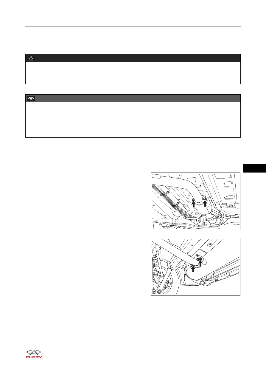
4. Remove the center pipe assembly.

a. Remove 2 coupling nuts (arrow), disconnect the 

connection between main catalytic converter assembly 
and center pipe assembly, and take off the gasket in 
the connecting part.

(Tightening torque: 50 ± 5 N·m)

b. Remove 2 spring bolts (arrow), disconnect the 

connection between center pipe assembly and muffler 
assembly, and take off the sphere flange grommet in 
the connecting part.

(Tightening torque: 50 ± 5 N·m)

WARNING

 The temperature of exhaust system is very high when engine is running. Before removal, make sure that 

engine has stopped running; otherwise, there is a risk of scald injury.

CAUTION

 When removing center pipe assembly, an assistant is needed to hold center pipe assembly. Prevent 

center pipe assembly from dropping to cause accidents during operation. 

 Be sure to wear necessary safety equipment to prevent accidents when repairing.
 Try to prevent body paint surface from being scratched during removal and installation. 

RT21110140

RT21110150

11–

16

11

c. Detach the diamond shaped hanger block (arrow) 

between center pipe assembly and body hook.

d. Remove the center pipe assembly.

Installation

Installation is in the reverse order of removal.

RT21110160

CAUTION

 If gasket is damaged, replace it, and remove foreign matter on joints and threads.
 If sphere flange grommet is damaged, replace it, and remove foreign matter on joints and threads.
 If there are cracks or leaks, replace the damaged parts.
 During installation, check that exhaust system components do not contact with muffler heat insulator I or 

vehicle underbody. Make sure that clearance between exhaust system components and muffler heat 
insulator I or vehicle underbody is more than 25 mm.

 Check for exhaust gas leaks. If gas leaks, tighten defective area to prevent leaking. Replace damaged 

parts as necessary.

11–

17

11

Muffler Assembly

Removal

1. Turn off all the electrical equipment and ignition switch.
2. Disconnect the negative battery cable.
3. Raise the vehicle to a proper height.
4. Remove the muffler assembly.

a. Remove 2 spring bolts (arrow), disconnect the 

connection between muffler assembly and center pipe 
assembly, and take off the sphere flange grommet in 
the connecting part.

(Tightening torque: 50 ± 5 N·m)

b. Detach the diamond shaped hanger block (1) 

between left side of muffler assembly and body hook.

c. Detach the hanger block III (2) between left side of 

muffler assembly and body hook.

WARNING

 The temperature of exhaust system is very high when engine is running. Before removal, make sure that 

engine has stopped running, otherwise, there is a risk of scald injury.

CAUTION

 When removing center pipe assembly, an assistant is needed to hold muffler assembly. Prevent muffler 

assembly from dropping to cause accidents during operation. 

 Be sure to wear necessary safety equipment to prevent accidents when repairing.
 Try to prevent body paint surface from being scratched during removal and installation. 

RT21110150

1

2

RT21110170

11–

18

11

d. Detach the diamond shaped hanger block (1) 

between right side of muffler assembly and body 
hook.

e. Detach the hanger block III assembly (2) between 

right side of muffler assembly and body hook.

f. Remove the muffler assembly.

5. Remove the hanger block III assembly. 

a. Remove 2 fixing bolts (arrow) from hanger block III 

assembly on the left side of muffler assembly.

(Tightening torque: 50 ± 5 N·m)

b. Remove the hanger block III assembly from the left 

side of muffler assembly.

c. Remove 2 fixing bolts (arrow) from hanger block III 

assembly on the right side of muffler assembly.

(Tightening torque: 50 ± 5 N·m)

d. Remove the hanger block III assembly from the right 

side of muffler assembly.

6. Remove the muffler assembly heat insulator.

a. Remove 4 clamping pieces (1) from the muffler 

assembly heat insulator I, and remove the muffler 
assembly heat insulator I.

b. Remove 4 clamping pieces (2) from the muffler 

assembly heat insulator II, and remove the muffler 
assembly heat insulator II. 

1

2

RT21110180

RT21110190

RT21110200

1

2

RT21110210


Content   ..  147  148  149  150   ..