Chery Tiggo 5 (T21). Manual - part 147


  Index      Chery     Chery Tiggo 5 (T21) - service repair manual 2014 year


Search            


Content   ..  145  146  147  148   ..


Chery Tiggo 5 (T21). Manual - part 147


11–

7

11

ON-VEHICLE SERVICE

Exhaust Manifold Assembly

Removal

1. Turn off all the electrical equipment and ignition switch.
2. Disconnect the negative battery cable.
3. Remove the engine trim cover assembly (

See page 10-10

).

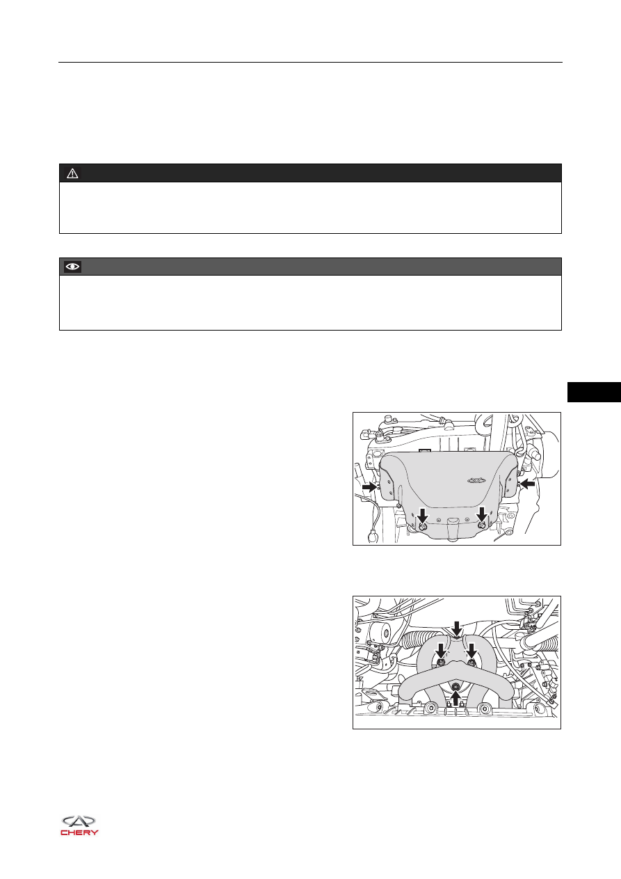
4. Remove the exhaust manifold heat insulator.

a. Remove 4 fixing bolts (arrow) from the exhaust 

manifold heat insulator.

(Tightening torque: 23 ± 2 N·m)

b. Remove the exhaust manifold heat insulator.

5. Remove the exhaust manifold assembly.

a. Remove 4 coupling nuts (arrow), disconnect the 

connection between exhaust manifold assembly and 
precatalytic converter assembly, and take off the 
gasket in the connecting part.

(Tightening torque: 50 ± 5 N·m)

WARNING

 The temperature of exhaust system is very high when engine is running. Before removal, make sure that 

engine has stopped running, otherwise, there is a risk of scald injury.

CAUTION

 Be sure to wear necessary safety equipment to prevent accidents when repairing.
 Try to prevent body paint surface from being scratched during removal and installation. 

RT21110020

RT21110030

11–

8

11

b. Remove 8 fixing nuts (arrow) from the exhaust 

manifold assembly.

(Tightening torque: 23 ± 2 N·m)

c. Remove the exhaust manifold assembly, and remove the gasket from the exhaust manifold assembly.

Inspection

1. Measure warpage on the surface of exhaust manifold 

assembly with a precision ruler and a feeler gauge. If 
warpage on the surface is greater than 0.5 mm, replace 
it.

2. Measure warpage on the surface of cylinder head 

exhaust side with a precision ruler and a feeler gauge. If 
warpage on the surface is greater than 0.04 mm, replace 
it.

3. Check that there are no scratches and roughness on 

exhaust manifold gasket. Otherwise, replace it.

RT21110040

RT21110050

RT21110060

RT21110070

11–

9

11

Installation

Installation is in the reverse order of removal.

CAUTION

 When installation is completed, check that there is no exhaust gas leakage between exhaust manifold 

assembly and cylinder head, precatalytic converter assembly.

11–

10

11

Precatalytic Converter Assembly

Removal

1. Turn off all the electrical equipment and ignition switch.
2. Disconnect the negative battery cable.
3. Remove the engine trim cover assembly (

See page 10-10

).

4. Remove the precatalytic converter assembly.

a. Take off and disconnect the upstream oxygen sensor 

connector (arrow) from the bracket.

b. Remove 4 fixing bolts (arrow) from the exhaust 

manifold heat insulator, and remove the exhaust 
manifold heat insulator.

(Tightening torque: 23 ± 2 N·m)

WARNING

 The temperature of exhaust system is very high when engine is running. Before removal, make sure that 

engine has stopped running, otherwise, there is a risk of scald injury.

CAUTION

 Be sure to wear necessary safety equipment to prevent accidents when repairing.
 Try to prevent body paint surface from being scratched during removal and installation. 

RT21090110

RT21110020


Content   ..  145  146  147  148   ..