Chery Tiggo 5 (T21). Manual - part 143


  Index      Chery     Chery Tiggo 5 (T21) - service repair manual 2014 year


Search            


Content   ..  141  142  143  144   ..


Chery Tiggo 5 (T21). Manual - part 143


10–

18

10

d. Remove the air filter assembly left fixing bolt (arrow). 

(Tightening torque: 7 ± 1 N·m)

e. Remove the air filter assembly right fixing bolt (arrow).

(Tightening torque: 7 ± 1 N·m)

f. Remove the air filter assembly from the bracket. 

HINT:
Make sure that connection between wire harness and air filter assembly is disconnected. 

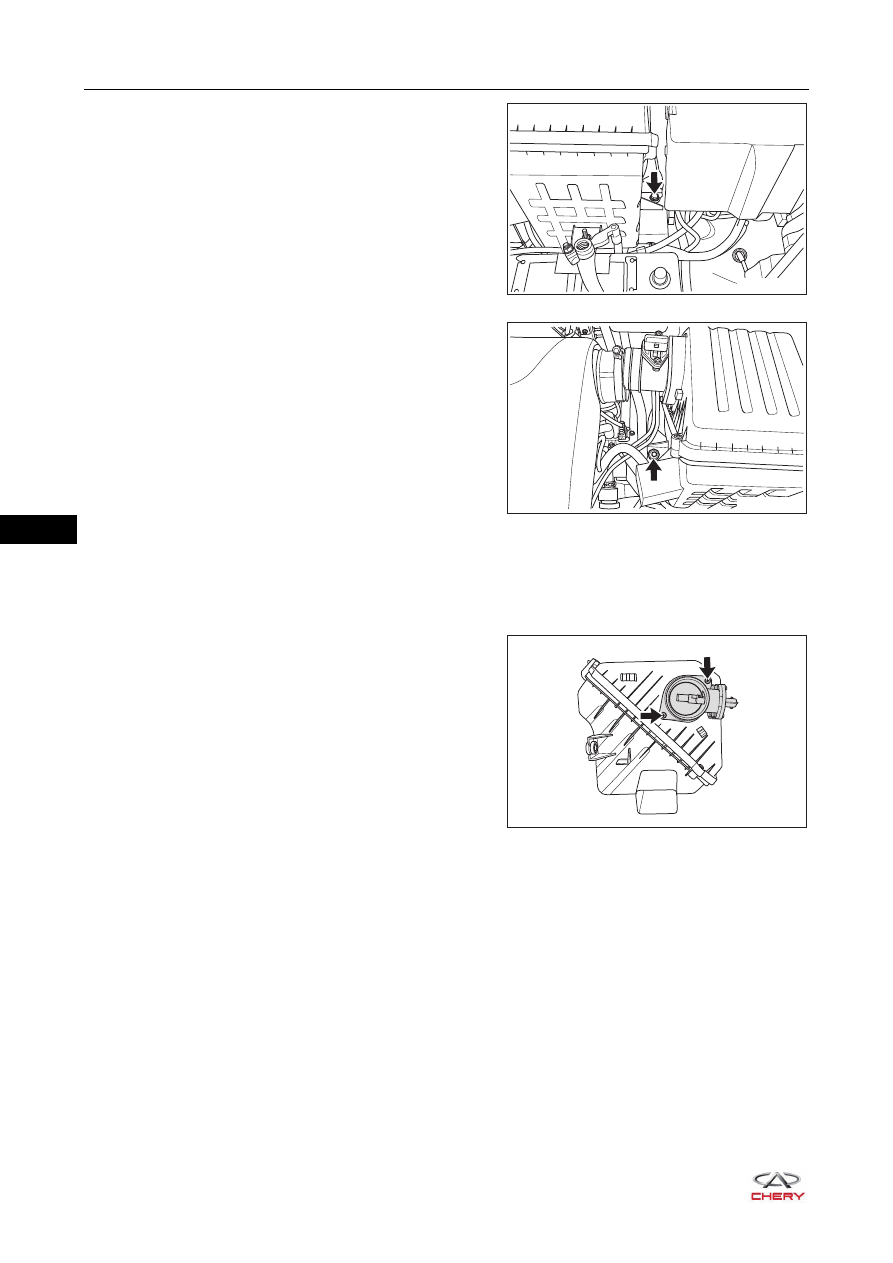
5. Remove the hot wire air flow meter. 

a. Remove 2 fixing bolts (arrow) from the hot wire air 

flow meter. 

(Tightening torque: 4.5 ± 0.5 N·m)

b. Remove the hot wire air flow meter from the air filter assembly. 

RT21100140

RT21100150

RT21100160

10–

19

10

6. Remove the air filter assembly bracket. 

a. Disconnect 3 wire harness clips from the air filter assembly bracket. 
b. Remove 3 fixing bolts (arrow) from the air filter 

assembly bracket. 

(Tightening torque: 7 ± 1 N·m)

c. Remove the air filter assembly bracket. 

Installation

Installation is in the reverse order of removal. 

RT21100170

10–

20

10

Electronic Throttle Assembly

On-vehicle Inspection

1. Check the electronic throttle assembly. 

a. When power is off, the throttle valve plate should be in 

NLP position. If you flip the valve plate by hand, it can 
rotate smoothly. If sticking occurs, which indicates 
internal components may be damaged, replace the 
electronic throttle assembly. 

b. Connect X-431 3G diagnostic tester to Data Link 

Connector (DLC). 

c. Turn ignition switch ON and turn on X-431 3G diagnostic 

tester.

d. Read data flow on X-431 3G diagnostic tester. 

 Release accelerator pedal.

 Depress accelerator pedal. 

If result is not as specified, check wire harness, ECM or 
replace electronic throttle assembly. 

Removal

1. Turn off all the electrical equipment and ignition switch. 
2. Disconnect the negative battery cable.
3. Remove the engine trim cover assembly (

See page 10-10

).

4. Remove the electronic throttle assembly. 

sensor voltage from throttle potentiometer 1

sensor voltage from throttle potentiometer 2

additive correction of the mixture adaptation

Voltage PWG potentiometer 1

Voltage PWG potentiometer 2

Doubled PWG potentiometer-2 voltage

multiplicative correction of the mixture adaptation

lambda controller output

Datastream name

Value

1.00

1.03

0.00

0.77

0.38

0.75

0.78

V

V

V

V

V

%

4.22

Unit

Datastream

RT21100171

Data Flow Name

Specification (V)

Throttle potentiometer 1 signal voltage 

0.78

Throttle potentiometer 2 signal voltage 

4.22

sensor voltage from throttle potentiometer 1

sensor voltage from throttle potentiometer 2

additive correction of the mixture adaptation

Voltage PWG potentiometer 1

Voltage PWG potentiometer 2

Doubled PWG potentiometer-2 voltage

Lambda controller output

multiplicative correction of the mixture adaptation

Datastream name

Value

1.00

1.03

0.00

4.60

2.30

4.61

4.29

V

V

V

V

V

%

0.71 

Unit

Datastream

RT21100172

Data Flow Name

Specification (V)

Throttle potentiometer 1 signal voltage 

4.29

Throttle potentiometer 2 signal voltage 

0.71

CAUTION

 Temperature of hood is very high when engine is running. Before removal, make sure engine has 

stopped running and hood has cooled down, otherwise, there is a risk of scald injury.

 Be sure to wear necessary safety equipment when repairing to prevent accidents.
 Try to prevent body paint surface from being scratched during removal and installation. 

10–

21

10

a. Loosen the worm clamp (arrow) and disconnect the 

connection between front inlet hose and electronic 
throttle assembly. 

(Tightening torque: 5 ± 0.5 N·m)

b. Disconnect the electronic throttle assembly connector 

(arrow).

c. Loosen the elastic clamp, and disconnect the connection 

between throttle body preheat water intake hose (1) and 
electronic throttle assembly.

d. Loosen the hose clamp, and disconnect the connection 

between throttle body preheat water outlet hose (2) 
and electronic throttle assembly.

e. Remove 4 fixing bolts (arrow) from the electronic 

throttle assembly. 

(Tightening torque: 8 + 3 N·m)

f. Remove the electronic throttle assembly and its gasket. 

RT21100180

2

1

RT21100190

CAUTION

 After disconnecting throttle body preheat water inlet hose and outlet hose, cover the hoses with wooden 

corks or equivalent to prevent coolant in hoses from flowing out.

 If your body contacts coolant accidentally, clean it with water immediately. If it is serious, please go to 

hospital.

 DO NOT allow engine coolant enter electronic throttle assembly. If the coolant enters, wipe them with a 

clean cotton yarn immediately. 

ENVIRONMENTAL PROTECTION

 Wasted coolant should be handled by the specialized department according to local laws and 

regulations. Never discard it at will.

RT21100200


Content   ..  141  142  143  144   ..