Chery Tiggo 5 (T21). Manual - part 144


  Index      Chery     Chery Tiggo 5 (T21) - service repair manual 2014 year


Search            


Content   ..  142  143  144  145   ..


Chery Tiggo 5 (T21). Manual - part 144


10–

22

10

Inspection

1. Check electronic throttle assembly gasket. 

Check electronic throttle assembly gasket for worn or 
bent. If there is worn or bent, replace electronic throttle 
assembly gasket. 

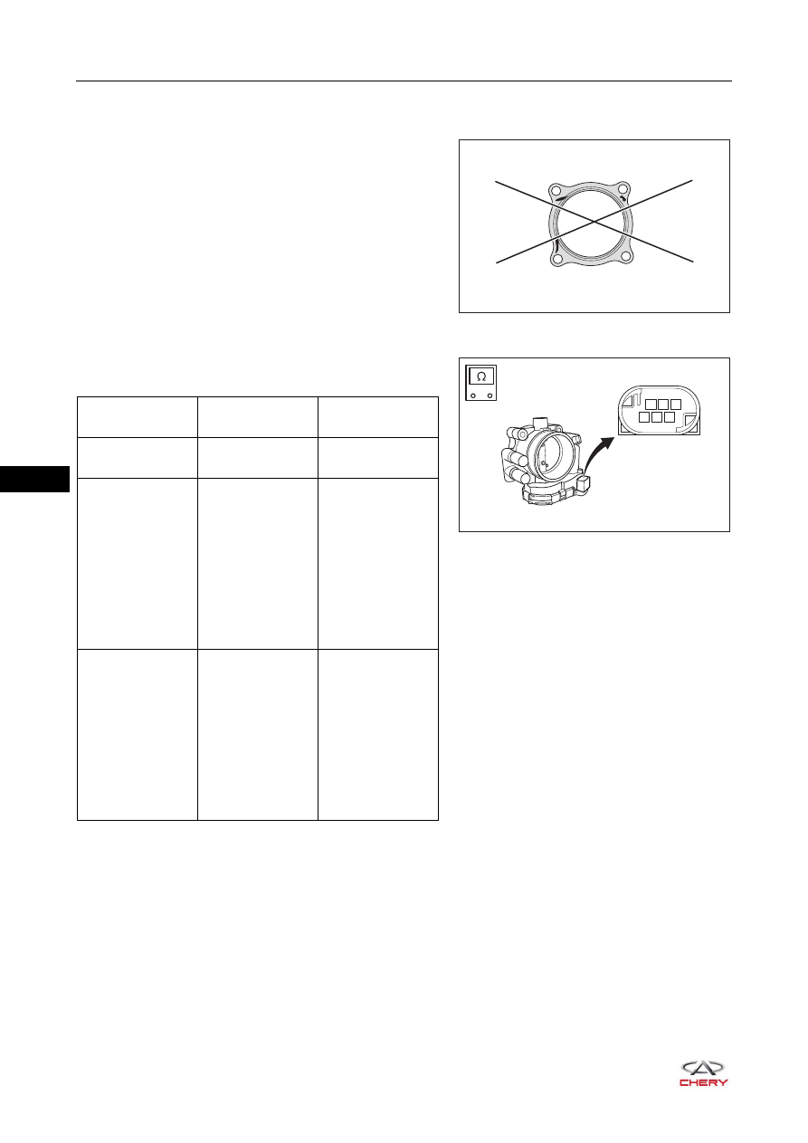
2. Check electronic throttle.

Measure electronic throttle resistance according to the 
table below.

Cleaning

Cleaning tool

1. Thin stick: used to support throttle valve plate for cleaning the carbon deposited on contact wall between 

valve plate and throttle. Please use plastic, wooden or bamboo thin stick. Do not use metal thin stick, 
avoiding scratching or deforming the valve plate.

2. Clean cloth or paper towel

RT21100210

RT21100211

1

2

3

4

5

6

-

+

Tester 

Connection

Adjustment

Specified 

Condition

Terminal 3 - 

Terminal 2

Normal 

temperature

1.067 kΩ

Terminal 6 - 

Terminal 2

Terminal 6 - 

Terminal 3

Rotate throttle

Resistance 

between terminal 

6 and terminal 2 

increases as 

throttle opens; 

resistance 

between terminal 

6 and terminal 3 

decreases as 

throttle opens.

Terminal 5 - 

Terminal 2

Terminal 5 - 

Terminal 3

Rotate throttle

Resistance 

between terminal 

5 and terminal 2 

decreases as 

throttle opens; 

resistance 

between terminal 

5 and terminal 3 

increases as 

throttle opens.

10–

23

10

Cleaning Process

1. Remove throttle body, and make the valve plate face 

upward in free condition. Avoid cleaner flowing into 
electronic element through valve plate shaft, resulting in 
functional failure. 

2. Start to clean when it is as shown in the illustration. 

3. Apply appropriate amount of cleaner to the inner wall of throttle valve body, and remove the carbon with a 

clean cloth. 

4. Support the throttle valve plate with thin stick, and clean 

the carbon on valve plate and throttle valve body inner 
wall. 

5. Turn over the throttle 180°, and perform cleaning with the same procedures as above. Repeat several 

times until it is clean. 

6. Push the valve plate by hand, and check if valve plate rotates smoothly. If it is stuck, clean the valve plate 

again following the cleaning procedures.

7. After cleaning, wipe off cleaner in throttle valve body with absorbent paper.

Installation

Installation is in the reverse order of removal. 

RT21100220

WARNING

 Cleaner is a kind of flammable and corrosive fluid. Follow safety cautions to prevent accidents, and avoid 

skin contacting with the cleaner. 

RT21100221

CAUTION

 Clean fitting surface of electronic throttle assembly.
 Perform throttle self-learning procedures after installation (

See page 06-19

). After self-learning completed, 

start vehicle and observe if it operates properly.

 Check and add engine coolant.

10–

24

10

Intake Manifold Assembly

Removal

1. Release fuel system pressure (

See page 08-10

). 

2. Turn off all the electrical equipment and ignition switch. 
3. Disconnect the negative battery cable. 
4. Remove the engine trim cover assembly (

See page 10-10

). 

5. Remove the fuel rail injector assembly (

See page 08-26

). 

6. Remove the electrical throttle assembly (

See page 10-20

). 

7. Remove the trim cover front bracket (

See page 10-11

). 

8. Remove the intake manifold assembly. 

a. Pull out the line assembly with PCV valve assembly 

from the PCV valve rubber boot in the direction of 
arrow as shown in the illustration.

b. Loosen the elastic clamp (1) and disconnect the 

connection between vacuum booster hose and intake 
manifold assembly. 

c. Loosen the elastic clamp (2) and disconnect the 

connection between canister solenoid valve outlet 
hose and intake manifold assembly.

d. Remove the intake manifold bracket fixing bolt 

(arrow). 

(Tightening torque: 18 ± 2 N·m)

CAUTION

 Temperature of hood is very high when engine is running. Before removal, make sure engine has 

stopped running and hood has cooled down, otherwise, there is a risk of scald injury. 

 Be sure to wear necessary safety equipment when repairing to prevent accidents. 
 Try to prevent body paint surface from being scratched during removal and installation. 

RT21100230

RT21100240

2

1

10–

25

10

e. Remove the fixing bolt (1) of oil dipstick on intake 

manifold assembly.

(Tightening torque: 8 ± 3 N·m)

f. Disconnect the starter field wire harness connector 

(2). 

g. Remove the fixing bolt (arrow) of the engine wire 

harness on cylinder head cover. 

(Tightening torque: 8 ± 3 N·m)

h. Remove 9 fixing nuts (arrow) from the intake manifold 

assembly.

(Tightening torque: 8 ± 3 N·m)

i. Move the engine wire harness away, and remove the intake manifold assembly. 

HINT:
While removing the intake manifold assembly, disconnect the intake camshaft variable timing control valve 
connector, knock sensor connector, back-up light switch and back-up light switch wire harness clip (for MT 
model). 

9. Disconnect the coupling joint (arrow) between line 

assembly and intake manifold assembly, and remove the 
line assembly (1) from the intake manifold assembly.

1

2

RT21100250

RT21100260

RT21100270

1

RT21100280


Content   ..  142  143  144  145   ..