Chery Tiggo 5 (T21). Manual - part 142


  Index      Chery     Chery Tiggo 5 (T21) - service repair manual 2014 year


Search            


Content   ..  140  141  142  143   ..


Chery Tiggo 5 (T21). Manual - part 142


10–

14

10

Air Filter Element

Removal

1. Turn off all the electrical equipment and ignition switch. 
2. Disconnect the negative battery cable. 
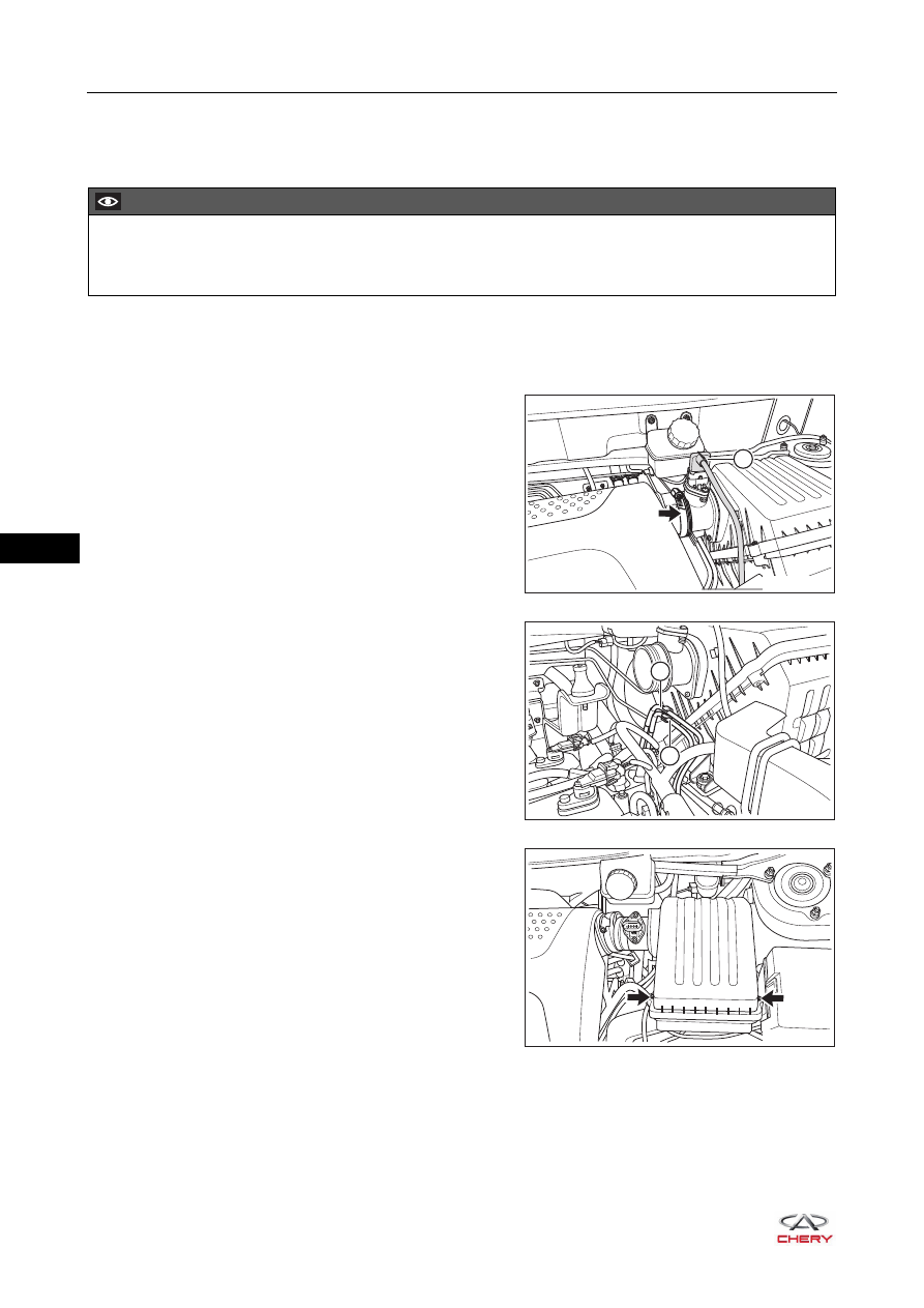
3. Remove the air filter element. 

a. Loosen the worm clamp (arrow) and disconnect the 

connection between rear intake hose and hot wire air 
flow meter.

(Tightening torque: 5 ± 0.5 N·m)

b. Disconnect the hot wire air flow meter connector (1). 

c. Move the inlet pipe II assembly (1) and fuel vapor tube 

III assembly (2) from the pipe clamp on the air filter 
upper housing. 

d. Remove 2 coupling screws (arrow) between air filter 

upper housing and lower housing. 

(Tightening torque: 1.3 ± 0.2 N·m)

e. Remove the air filter upper housing. 

CAUTION

 Be sure to wear necessary safety equipment when repairing to prevent accidents. 
 Try to prevent body paint surface from being scratched during removal and installation. 

RT21100090

1

1

2

RT21100100

RT21100110

10–

15

10

f. Take out the air filter element.

Installation

1. Clean air filter upper housing and lower housing. 
2. Install a new air filter element. 
3. Other installation procedures are in the reverse order of removal. 

RT21100120

ENVIRONMENTAL PROTECTION

 Unneeded air filter element should be handled by the specialized department according to local laws and 

regulations. Never discard it at will. 

10–

16

10

Air Induction Pipe Assembly

Removal

1. Turn off all the electrical equipment and ignition switch. 
2. Disconnect the negative battery cable.
3. Remove the air induction pipe assembly. 

a. Remove 2 fixing bolts (arrow) from the air induction 

pipe assembly. 

(Tightening torque: 7 ± 1 N·m)

b. Remove the air induction pipe assembly from the air filter assembly. 

Installation

Installation is in the reverse order of removal.

CAUTION

 Be sure to wear necessary safety equipment when repairing to prevent accidents. 
 Try to prevent body paint surface from being scratched during removal and installation. 

RT21100130

10–

17

10

Air Filter Assembly & Bracket

Removal

1. Turn off all the electrical equipment and ignition switch. 
2. Disconnect the negative battery cable. 
3. Remove the air induction pipe assembly. 

a. Remove 2 fixing bolts (arrow) from the air induction 

pipe assembly.

(Tightening torque: 7 ± 1 N·m)

b. Remove the air induction pipe assembly. 

4. Remove the air filter assembly. 

a. Loosen the worm clamp (arrow) and disconnect the 

connection between rear intake hose and hot wire air 
flow meter.

(Tightening torque: 5 ± 0.5 N·m)

b. Disconnect the hot wire air flow meter connector (1). 

c. Move the inlet pipe II assembly (1) and canister 

solenoid valve inlet pipe (2) from the bracket on air 
filter upper housing. 

CAUTION

 Be sure to wear necessary safety equipment when repairing to prevent accidents. 
 Try to prevent body paint surface from being scratched during removal and installation. 

RT21100130

RT21100090

1

1

2

RT21100100


Content   ..  140  141  142  143   ..