Chery Fora (Elara A520). Manual - part 18
Chery Service Manual for A520 Body Dimension and Accessories
11
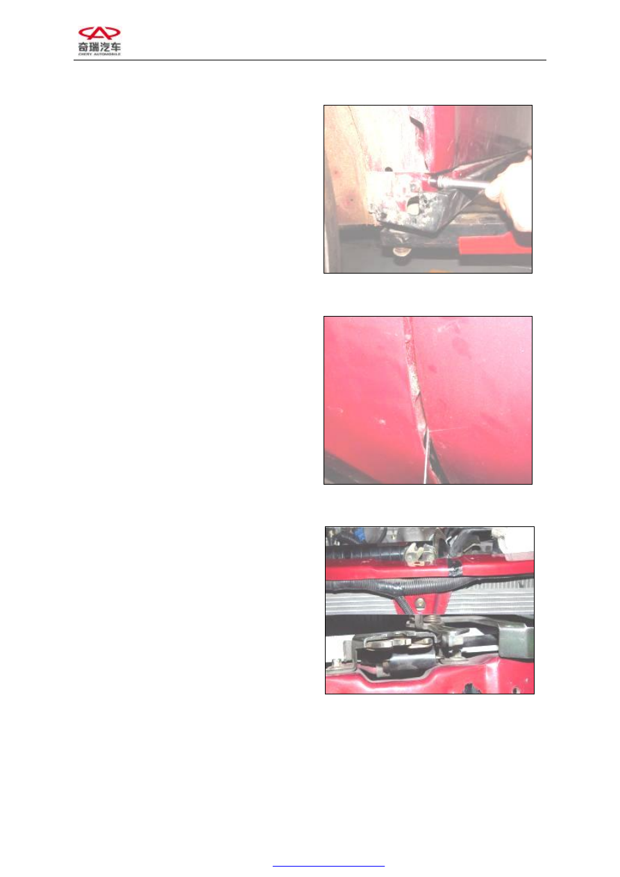
Figure 26
4. Remove the bolts connecting the body
from inside. (You can remove the tire
when the operation space is too narrow).
Figure 27
VI. DISASSEMBLING THE ENGINE
HOOD CONTROL CABLE:
1. Remove the left lower trim board of the
instrument desk (see Disassembling the
instrument desk)
2. Remove the lining of the left fender (see
Disassembling the fender)
3. Remove the engine hood lock to loosen
and take out the engine hood control
cable
Assembly requirements: Adjust the front
engine hood lock to make sure that the front
engine hood peripheral clearance is uniform
9±1 mm with equal height at top and bottom.
The tightening torque of the front engine
Figure 28