Chery Amulet Engine. Manual - part 4


  Index      Chery     Chery Amulet Engine - manual


Search            


Content   ..  1  2  3  4  5  ..


Chery Amulet Engine. Manual - part 4


2】. Upper and lower timing gear cover assemblies removal and installation 


Removal: 
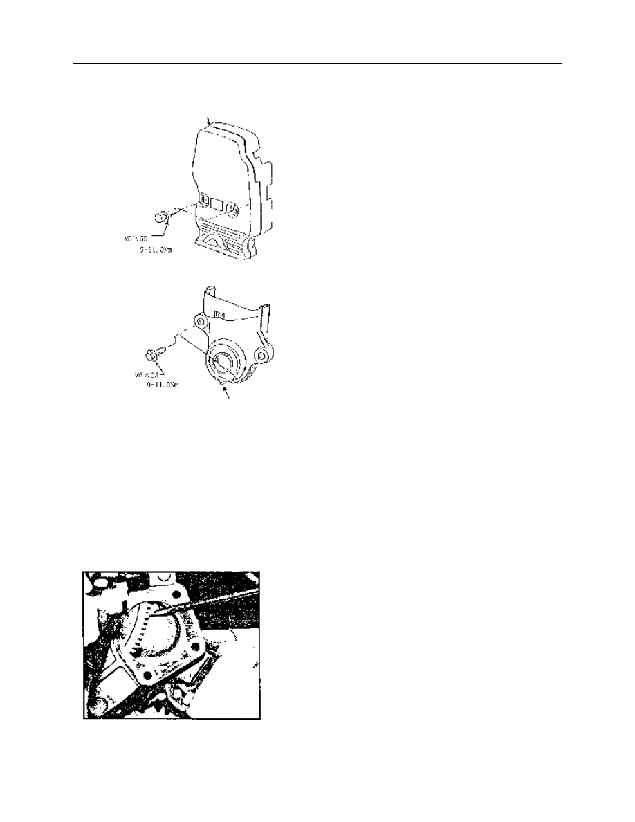
——Loosen and remove 2 bolts for upper timing 
gear cover assembly. 
——Remove upper timing gear cover and seal 
assembly. 
——Remove seal gasket and shot nail from 
upper timing gear cover. 
——Remove crankshaft pulley. 
——Loosen and remove 2 bolts for lower timing 
gear cover assembly. 
——Remove lower timing gear cover and seal 
gasket assembly. 
——Remove shot nail and seal gasket from 
lower timing gear cover. 
Installation: 
——Clean lower timing gear cover. 
——Mount new seal gasket with shot nail or 
glue on lower timing gear cover. 
——Install lower timing gear cover and seal 
gasket on crankshaft,finger screw in 2 bolts and                                   

tighten to 9.0—11Nm. 
——Clean upper timing gear cover. 

——Mount new seal gasket with shot nail or glue 
on lower timing gear cover. 
——Install upper timing gear cover seal gasket 
with 2 bolts on cylinder block,tightening torque 
is 9—11Nm. 

3】. Crankshaft pulley removal and installation 


Removal: 
——If engine is equipped with starter,remove 
three M10×30 or M10×35 bolts and remove 
starter. 
——Block flywheel ring gear with a appropriate 
screwdriver or lever, preventing crankshaft from 
rotating. 
——Loosen crankshaft pulley mounting bolts, 
remove bolt and cushion block. 

——Pull out pulley, if necessary, puller may be   

used. 

Upper timing gear cover assembly 

Bolt 

Tightening 
torque 

Tightening 
torque


Lower timing gear cover assembly 

Fig.4 

Fig.5 


Installation: 
——Clean pulley and crankshaft journal,remove the 
oil in pulley groove . 
——Install pulley on crankshaft journal, aligning 
keyway with semicircular key. 
——Slip cushion block onto bolts and finger screw 
in. 
——Block flywheel ring gear with screwdriver, 
preventing crankshaft from turning. 
——Tighten bolts to 100—115Nm. 


4】. Valve cover and seal gasket removal and installation 


Removal: 
——Remove 9 bolts and butterfly gasket. 
——Remove valve cover and seal gasket 
assembly. 
——Remove seal gasket. 


B

u

tte

rf

ly

 w

a

sh

e

Pulley 

Tightening torque 

Bolt 

Valve cover 

Fig. 7 

V

a

lv

e


c

o

v

e

se

a

l g

a

sk

e

Fig.6 

Fig.8   

Installation: 

——Clean cylinder head and valve cover 
contacting surface. 
——Push the wedge of valve cover seal gasket 
into appropriate valve cover groove, 
integrating valve cover with seal gasket. 


——Install valve cover and seal gasket 
assembly on cylinder head. 
——Install 9 hexagon head bolts of long 
column end with butterfly gasket,finger screw 
them into cylinder head. 
——Tighten bolts in two steps in order as 
diagram showed. 

Step 1:Tighten to 4.0—6.0Nm 
Step 2:Tighten to 8.0—10.0Nm 


5】. Timing belt removal, installation and adjustment 

 
Removal: 
——Rotate crankshaft to no.1 cylinder compression TDC. 
——Loosen 2 tension pulley mounting bolt (as arrow 
indicated in diagram),push tension pulley aside with a large 
screwdriver. 
——To release belt tension,tighten 2 tension pulley mounting 
bolts with tension pulley in this position. 
——To reuse belt,mark the direction of belt rotation and 
make reference mark on crankshaft gear and camshaft gear 
matching teeth,remove belt from camshaft gear, water pump 
gear and crankshaft gear. 


Fig.11 

Fig.12 


Fig.9 

Fig. 10 

Note:With belt removed,  don't turn gear excessively,or piston 
head and valve may be damaged for contacting. 
——If belt need to be reused  ,check for improper 
wear ,delaminate crack (particularly at the foot of teeth) or dirt. If 
lightly suspected, replace it. 
Installation and adjustment: 
——Crankshaft should be positioned at no.1 cylinder TDC,if 
necessary, crankshaft may only be turned slightly for adjustment 
and blocked at flywheel ring gear. 
 
——Engage timing belt tooth with crankshaft grooves,and pull 
belt up straight to the right engaging belt with cam gear grooves.                 
During the installation of used belt, insure belt is in the right 
direction and match belt with appropriate tooth. 
With belt installed, 2 gears should not make any movement. 
——Pull belt around tension pulley carefully,engage belt tooth 

with gear teeth grooves. 
Recheck both gears, there should be no movement. 
——Loosen 2 tension pulley mounting bolts,push tension pulley 
right to the extreme (viewed from the direction of pulley ),

tighten 

2 tension pulley mounting bolts and loosen crankshaft locking 
device. 
——Rotate crankshaft clockwise (viewed from the pulley end) 2 
turns until no.1 cylinder reaches its TDC of compression. 
——Grab the midway of the right side belt between crankshaft 
gear and camshaft gear with thumb and forefinger. If belt tension 
is as specified, belt may be twisted 90°.                 
 
To adjust belt tension,loosen 2 tension pulley mounting bolts and 
push tension pulley right side using screwdriver as push rod,then 
tighten mounting bolts and rotate crankshaft.    Recheck tension. 
It may take 2- 3 times before tension is as specified. After 
adjustment, tighten tension pulley mounting bolts to 16—20Nm. 
 
——It is only a approximate method to adjust belt,and belt 
tension should be checked as soon as possible by professionals 
with special tools . 


Fig.13 

Fig.14 


Content   ..  1  2  3  4  5  ..