Chery Amulet Engine. Manual - part 5
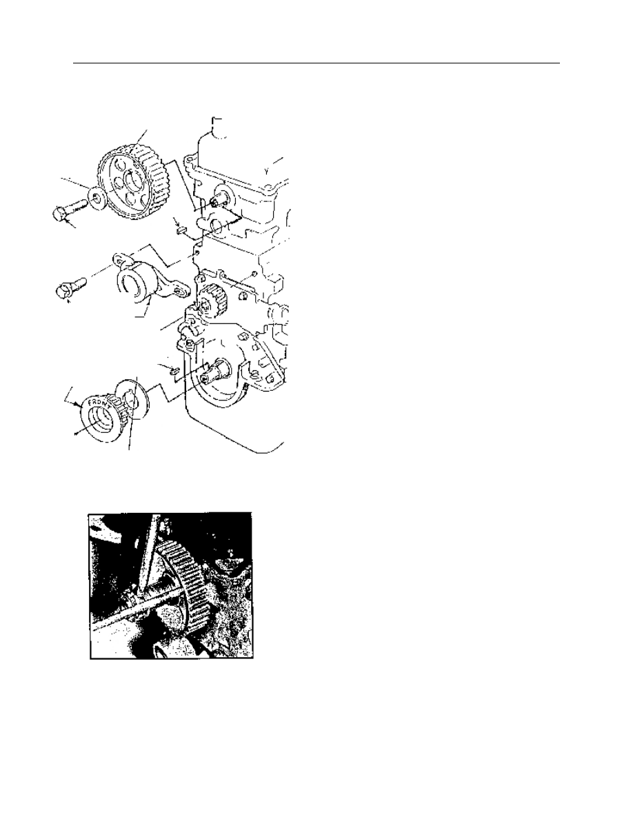
【6】. Tension pulley, crankshaft gear and camshaft gear removal, check and installation
1. Tension pulley
Removal:
——Rotate crankshaft to no.1 cylinder
compression TDC.
——Remove belt.
——Loosen 2 tension pulley mounting bolts,
push tension pulley aside to release belt tension
with a large screwdriver.
——Remove 2 mounting bolts and take out
tension pulley.
Installation:
——Check bearing for rotating freely by
turning tension pulley,bearing end play and
radial clearance, if suspected, replace
appropriate parts immediately.
——Crankshaft should be positioned at no.1
cylinder compression TDC.
——Install belt tension pulley,finger screw in 2
mounting bolts, then tighten to 16—20 Nm.
2. Camshaft gear.
Removal:
——Rotate crankshaft to no.1 cylinder
compression TDC
——Remove belt.
——Insert a lever into one of the camshaft gear
holes to block camshaft,then loosen gear bolt
and remove bolt and cushion block.
Note:During reinstallation,new bolt should be
applied , remove camshaft gear.
——Camshaft gears are not permitted to be
exchanged between 478 engine and 480 engine,
during replacement, the mark on the original
gear should be referred.
Crankshaft gear
Tension pulley
Timing gear
Key
Cushion
Bolt M12*1.5*30
Tightening torque52-60n.m
Key
Bolt M8*25
Tightening
torque16-20Nm
Fig.15
Fig.16