Snowmobile Ski Doo REV SERIES (2004 year). Manual - part 79


  Index      Snowmobiles / ATV     Snowmobile Ski Doo REV SERIES - service manual 2004 year


Search            


Content   ..  77  78  79  80   ..


Snowmobile Ski Doo REV SERIES (2004 year). Manual - part 79


Section 08 REAR SUSPENSION
Subsection 02 (SC-10 III SUSPENSION)

529 035 727

A32F1NA

When removing and retightening the tire valve
acorn nut use minimal torque. When the cap is
over tightened and subsequently removed it may
prematurely break the seal of the tire valve to the
shock body and cause a loss of nitrogen charge
without being noticed. If you suspect this has
happened then recharge the shock as a precau-
tion. Inspect the tire valve cap before installation
to ensure that the internal rubber gasket is in its
proper position.

Adding Gas Pressure

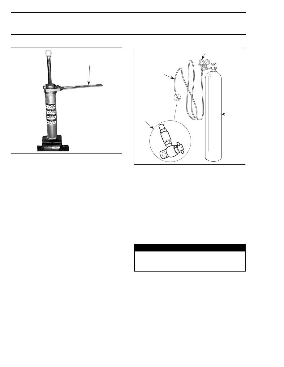
Nitrogen (N) can now be added to damper body.

4

2

1

3

A06F0QA

1. High pressure hose
2. 2 stage regulator, delivery pressure range 2070 kPa (300 PSI)
3. High pressure cylinder filled with industrial grade nitrogen
4. Valve tip (P/N 529 035 570) permanently installed

NOTE: Never substitute another gas for nitrogen.
Nitrogen has been selected for its inert qualities
and will not contaminate the gas chamber of the
shock.

Preset your pressure regulator to 2070 kPa
(300 PSI) nitrogen (N), this gas pressure will re-
store the correct pressure for your damper.

CAUTION: Do not exceed the recommended
pressure values.

WARNING

Whenever working with high pressure gas,
use eye wear protection. Never direct gas
pressure toward anybody.

Use appropriate inflation tool.

Needle Valve Type Shock

Install the gas refill needle type shock tool
(P/N 503 190 102) on valve tip (P/N 529 035
570). Set the regulator pressure on the nitrogen
cylinder as per the shock requirement.

308

mmr2004-Rev

Section 08 REAR SUSPENSION

Subsection 02 (SC-10 III SUSPENSION)

Mount the shock on vise. Remove screw on top
of valve. Place the needle guide of gas refill tool
on the shock valve. While depressing the detent
pin of the gas refill tool and pushing forward the
needle assembly, insert the needle through the
rubber core of the pressure valve assembly of the
shock.

503 190 102

A32F38A

529 035 570

NOTE: For replacement of the needle or filling the
shock, carefully follow the instructions provided
with the gas refill needle type tool kit (P/N 503 190
102).

On some models, rubber may pop out of needle
valve when inserting tool needle. If so, remove
valve core and rubber then, reinstall rubber with
its larger diameter last.

1

A32F1SA

1. Larger diameter

When the shock is filled with gas, install back the
screw on top of the valve.

All Shock Types

NOTE: Carefully inspect damper for gas or oil
leaks. Any leaks must be corrected before con-
tinuing.

Damper gas pressure cannot be confirmed by
using a pressure gauge. The volume of gas in the
shock is very small, and the amount lost during
gauge installation will lower the pressure too
much and require refilling.

After recharging is complete the rebuilt shock
should be bench-tested.

Stroke the shock to

ensure full travel and smooth compression and
rebound action. If the shaft moves in or out er-
ratically this could indicate too much air is trapped
inside. If the shaft will not move or has partial
travel then it may be hydraulically locked. In ei-
ther event the shock must be rebuilt again. Pay
particular attention to the placement of the IFP,
quantity of oil and shim stack/piston assembly.

INSTALLATION

Install assembled suspension into track with front
portion first.

Insert rear portion of suspension into track.

Bolt front arm and rear arm.

Adjust track tension.

RIDE ADJUSTMENT

Refer to Operator’s Guide.

LUBRICATION

Lubricate front and rear arms at grease fittings
using suspension synthetic grease (P/N 293 550
033).

A32F16A

SC-10 III: 6 GREASE FITTINGS

mmr2004-Rev

309

Section 08 REAR SUSPENSION

Subsection 03 (DRIVE AXLE)

DRIVE AXLE

A32D1KT

15 N•m

(133 lbf•in)

Suspension

synthetic

grease

1

2

3

11

10

9

8

7

5

6

6

5

4

Suspension

synthetic

grease

mmr2004-Rev

311

Section 08 REAR SUSPENSION
Subsection 03 (DRIVE AXLE)

REMOVAL

Remove battery (if so equipped) to gain access,
refer to BATTERY section.

Drain oil from chaincase.

Remove chaincase

cover. Release drive chain tension.

A32D0YA

Raise and block rear of vehicle off the ground.

Remove suspension. Refer to proper subsection.

On some models, track can be held in tunnel using
a rod in place of center idler wheel axle.

A32D0ZA

1

TYPICAL
1. Rod

Remove driven pulley. Refer to DRIVEN PULLEY.

Remove speedometer sensor no.

11, outer

flange no. 10 and circlip no. 9 from left side.

Unscrew then pull speedometer magnetic adapter
no. 4 from drive axle.

1

A33D17A

1. Circlip

Apply parking brake.

Remove chain and sprockets then circlip from
right side.

Release drive axle sprocket from track and at the
same time, push the drive axle no. 3 toward the
right side. Drive axle bearing no. 1 in chaincase
will fall off.

Sprocket and Half-Sprocket

To remove press fit sprockets no. 5, 6, use a press
and a suitable support as illustrated.

A33D0LA

1. Support sprocket near hub

312

mmr2004-Rev


Content   ..  77  78  79  80   ..