Snowmobile Ski Doo REV SERIES (2004 year). Manual - part 78


  Index      Snowmobiles / ATV     Snowmobile Ski Doo REV SERIES - service manual 2004 year


Search            


Content   ..  76  77  78  79   ..


Snowmobile Ski Doo REV SERIES (2004 year). Manual - part 78


Section 08 REAR SUSPENSION
Subsection 02 (SC-10 III SUSPENSION)

Place shock absorber in a position where external
gas reservoir opened extremity is blocked. Refer
to following photo.

1

A32F3ZA

2

1. Tool
2. Reservoir opened extremity blocked by leaning on work bench

With a low pressure hand pump, pressurize shock
absorber until external reservoir piston pops-out.

NOTE: Use towels to prevent damaging external
reservoir piston when it pops-out.

WARNING

Whenever using compressed air, use an
O.S.H.A. approved air gun and wear protec-
tive eye wear.

Thoroughly clean, with a typical cleaning solution,
and blow dry using low pressure air. Carefully in-
spect the damper body for any imperfections or
signs of wear in the damper bore.

Replace damper body if wear is identified.

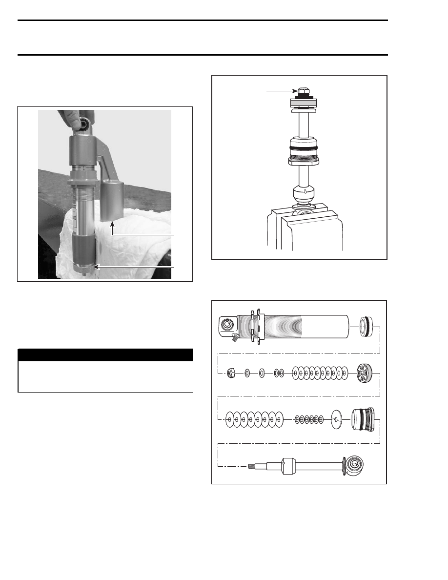
Holding the damper rod assembly in a bench vise,
begin piston and valve removal.

A06F0UA

A

A. Remove damper nut

Always arrange parts removed in the sequence of
disassembly.

A06F0VA

NOTE: As a general rule we suggest replacing
the damper rod lock-nut after 4 rebuilds to ensure
good Iocking friction and use Loctite 271 each
time.

304

mmr2004-Rev

Section 08 REAR SUSPENSION

Subsection 02 (SC-10 III SUSPENSION)

NOTE: If revalving is to be done, it is imperative
that you identify the original shim pack (size and
number of shims). The seal carrier need not be
removed if only revalving is to be done.

Shims can be measured by using a vernier caliper
or a micrometer.

NOTE: All shims should be carefully inspected and
any bent or broken shims must be replaced for the
shock to function properly.

After the new or replacement shim pack has
been selected, reassemble in the reverse order
of disassembly. Torque piston nut to 27 - 29 N•m
(20 - 21 lbf•ft).

A32F1WA

4

1

2

3

1. Damper nut
2. Spacer
3. Stopper with its round edge facing nut
4. Shim pack

CAUTION: The damper rod nut can only be
reused 4 times, then, must be replaced. Do
not substitute this part for non - O.E.M. use
Loctite 271 on nut each time.

This (these) spacer washer(s) must be used as
shown to ensure damper rod nut does not bottom
out or contact shaft threads.

Rebound valve stopper with round edge facing
nut.

NOTE: Rebound shim stack must not reach into
threads of damper shaft. Spacer under damper
shaft nut is used to prevent damper shaft nut from
bottoming on threads.

A32F1XA

1

2

3

4

5

6

1. Rebound dampening shim pack
2. Rebound dampening shim pack
3. Piston
4. Compression dampening shim pack
5. Compression dampening shim pack
6. Stopper

If the seal carrier assembly is replaced, use seal
pilot to guide seal over damper shaft. Lubricate
seal carrier guide pilot before use.

CAUTION: Failure to use seal pilot will result in
seal damage.

Reassemble damper rod assembly, taking care to
properly assemble shim packs as required for your
dampening needs. Ensure that the shaft piston
is installed with the slits/larger intake holes facing
the rebound shim stack.

A06F12C

1

1. Seal guide

mmr2004-Rev

305

Section 08 REAR SUSPENSION
Subsection 02 (SC-10 III SUSPENSION)

If floating piston has been removed, reinstall float-
ing piston into damper body (ensure that valve
core has been removed). Use Molykote G-n paste
(P/N 711 297 433) to ease O-ring past damper
body threads with floating piston guide.

CAUTION: Failure to install IFP correctly could
result in shock damage.

1

2

A06F14C

1. Push (slowly) by hand
2. Floating piston guide

NOTE: Lubricate inside of piston guide with
Molykote G-n paste (P/N 711 297 433).

Install floating piston to the proper depth refer to
following the table.

On all HPG take apart shocks, the floating piston
is installed hollow side up.

A27F0FD

A

A. Installation distance for floating piston installation

SHOCK P/N

INSTALLATION

DISTANCE OF

FLOATING PISTON

mm

505 070 903

44.5

505 070 904

44.5

505 070 937

44.5

505 070 938

44.5

503 190 016

128

503 190 247

128

503 190 289

130

503 190 008

132

503 190 019

132

503 190 201

132

503 190 015

134

503 190 017

134

503 190 226

134

505 070 753

176

503 190 007

185

503 190 205

185

503 190 290

185

505 070 966

186

505 071 111

186

503 190 020

187

503 190 024

187

503 190 013

188

503 190 248

188

NOTE: If the floating piston is installed too far into
the damper body, light air pressure through valve
(with core removed) will move piston outward.

NOTE: Reinstall tire valve core after IFP has been
installed at correct height and before adding oil.

WARNING

Whenever using compressed air exercise ex-
treme caution, cover damper opening with
shop cloth to reduce chance of possible in-
jury.

306

mmr2004-Rev

Section 08 REAR SUSPENSION

Subsection 02 (SC-10 III SUSPENSION)

CAUTION: Moisture laden compressed air will
contaminate the gas chamber and rust floating
piston.

WARNING

Always wear protective eye wear whenever
using compressed air.

Fill the shock with Bombardier HPG shock oil
(P/N 293 600 035) to approximately 10 mm
(.393 in), from the base of seal carrier threads.

1

A06F15B

1. Fill to 10 mm (.393 in)

NOTE: Although we do not measure the exact
amount of oil added to the damper, approximately
252 mL (8.52 oz. U.S.) will be used.

Carefully insert damper rod into the damper body.
Lightly oil damper piston seal ring with shock oil
to ease installation.

A06F16A

NOTE: Some shock oil will overflow when in-
stalling damper. Wrap damper with shop cloth to
catch possible overflow oil.

CAUTION: Use care when passing piston into
damper body at damper body threads.

Slight oscillation of damper rod may be required to
allow piston to enter damper body bore.

Slowly push piston into damper body. Slight up
and down movement may be required on short
stroke to allow all air to pass through piston as-
sembly. The gentle tapping of a small wrench, on
the shock eye, may help dislodge air trapped in
the submersed piston. Be careful not to drive the
shaft any deeper into the oil than is necessary to
just cover the shim stack.

NOTE: Fast installation of the damper rod may dis-
place the floating piston from its original position.
This must not occur if the damper is expected to
perform as designed.

With damper rod piston into oil, TOP OFF damper
oil volume. Oil level should be to damper body
thread base.

Screw Cap Types of Shock

Seal carrier assembly can now be threaded into
damper body. This should be done slowly to
allow weapage of oil and to minimize IFP dis-
placement. Torque seal carrier to 90 to 100 N•m
(66 to 74 lbf•ft).

Snap Ring Cap Types of Shock

Seal carrier assembly can now be pushed into
damper body to pass snap ring grove. Install snap
ring into groove.

Tap the cap on the shock body.

All Types of Shocks

After the seal carrier is fully in place avoid pushing
the shaft into the body until the nitrogen charge is
added.

mmr2004-Rev

307


Content   ..  76  77  78  79   ..