Snowmobile Arctic Cat (2008 year). Manual - part 67
3-12
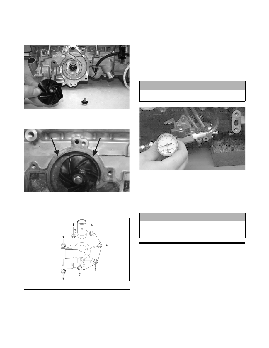
9. Place the impeller into position and secure with a
cap screw and washer. Be sure the rubber side of
the washer is directed towards the impeller. Apply
blue Loctite #243 to the threads of the cap screw
and tighten to 8 ft-lb.
FS225
10. Apply sealant to the crankcase seam; then install
the alignment pins into the crankcase (if removed).
FC133A
11. Position the O-ring into the water pump cover;
then install the cover. Install the cap screws; then
using the pattern shown, tighten to 8 ft-lb.
0742-257
Pressure Testing Engine
1. Test the engine for air leaks using the following
procedure and Engine Leak-Down Tester Kit.
A. Install a plug into each intake-manifold port
and tighten the flange clamps securely.
B. Place a rubber plug and cover on each exhaust
port and secure.
NOTE: On APV equipped engines, install the APV
cover plates.
C. Connect the tester pump to an impulse fitting
on the crankcase; then plug any remaining
impulse fittings and pressurize the crankcase to
8 psi and close the valve.
AN128D
D. Monitor the pressure gauge. The pressure must
not drop at a rate of more than 1 psi per minute.
E. If the pressure drops faster than specified,
inspect for an air leak with soapy water or by
completely submerging the pressurized engine
in clean fresh water. Repair as needed.
Liquid Cooling System
(500/600/800/1000 cc)
The liquid cooling system consists of heat exchangers,
water pump, coolant temperature sensor, and thermo-
stat. The system should be inspected for leaks or dam-
age whenever an overheating problem is experienced.
DRAINING COOLING SYSTEM
(Crossfire/M-Series)
1. Using a piece of cardboard to protect the hood and
belly pan, tip the snowmobile on its PTO-side.
2. From beneath the front end, remove the self-tap-
ping screws securing the skid plate to the chassis.
! CAUTION
DO NOT exceed 8 psi pressure or damage to the
seals will result.
! CAUTION
When submerging the engine to test for air leaks, all
external electrical components must be removed to
avoid damage.