Snowmobile Arctic Cat (2008 year). Manual - part 65


  Index      Snowmobiles / ATV     Snowmobile Arctic Cat - service manual 2008 year


Search            


Content   ..  63  64  65  66   ..


Snowmobile Arctic Cat (2008 year). Manual - part 65


3-4

4. Rotate the fan drive pulley clockwise while

observing the other two holes in the pulley. When

they align with the two holes in the flywheel, start

the remaining two mounting cap screws.

5. Tighten the three cap screws only to position the

fan drive pulley on the flywheel; then remove the

three cap screws and install the recoil starter pul-

ley. Apply red Loctite #271 to the threads of the

three cap screws and install them into the fly-

wheel. Tighten the three cap screws evenly to 6-

9 ft-lb.

6. Check the fan belt tension. Adjust as necessary.

7. Install the fan cover and secure with six screws.

Tighten the screws to 8 ft-lb.

8. Install the recoil starter. Secure with four cap

screws. Tighten to 8 ft-lb.

REPLACING FAN BELT

1. Remove the fan cover and the recoil starter.

 2. Remove the three cap screws securing the recoil

starter pulley and the fan drive pulley to the fly-

wheel.

3. Remove the fan drive pulley and fan belt from the

engine.

4. Place the new fan belt into position on the upper

pulley.

5. Place the fan drive pulley onto the fan belt and

align one of its holes with one of the mounting

holes in the flywheel; then start a cap screw into

the aligned hole and finger-tighten.

6. Rotate the fan drive pulley clockwise while

observing the other two holes in the pulley. When

they align with the two holes in the flywheel, start

the remaining two cap screws.

7. Tighten the three cap screws only to position the

fan drive pulley on the flywheel; then remove the

three cap screws and install the recoil starter pul-

ley. Apply red Loctite #271 to the threads of the

three cap screws and install into the flywheel.

Tighten the three cap screws evenly to 10 ft-lb.

AB040

„NOTE: With the new belt installed, check fan belt
tension (see Checking Belt Tension).

8. Install the fan cover. Tighten the screws to 8 ft-lb.

Install the recoil starter. Tighten the cap screws to

8 ft-lb.

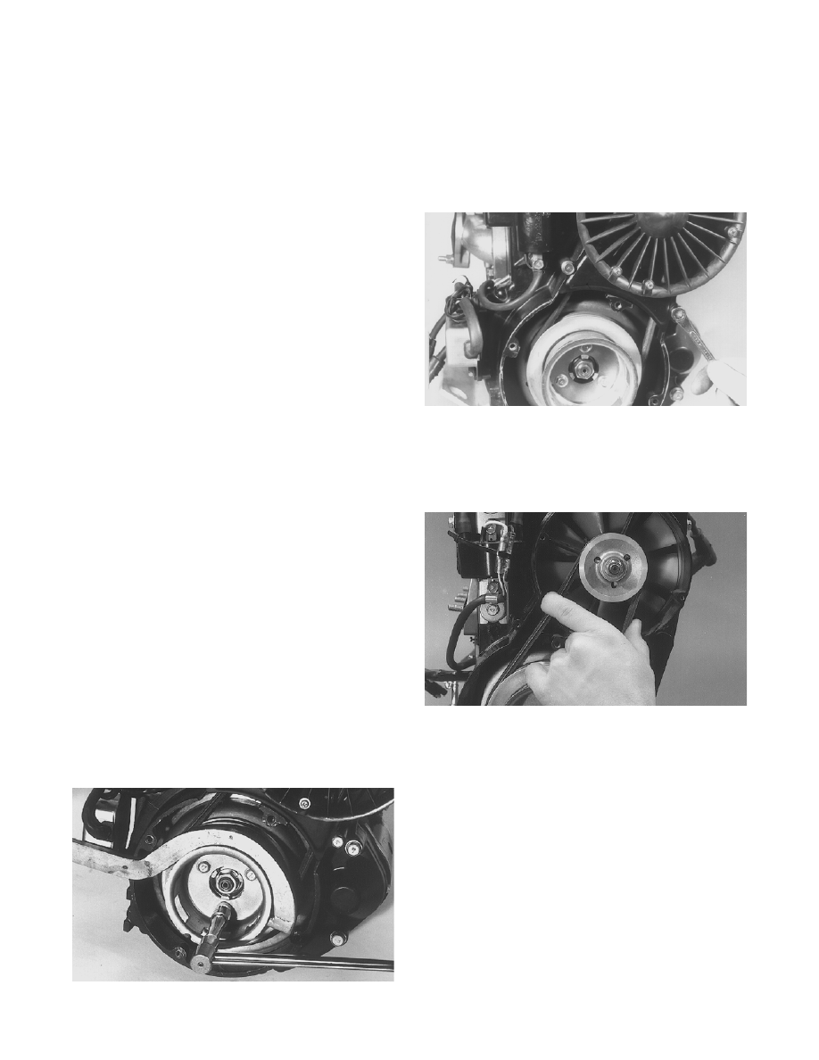
CHECKING BELT TENSION

1. Remove the fan cover.

AB075

2. Squeeze the belt at midspan and observe the belt

deflection. The maximum belt deflection on either

side must not exceed 6 mm (1/4 in.). If the deflec-

tion is not within specifications, adjust the belt

tension.

B075

3. Install the fan cover. Tighten the screws to 8 ft-lb.

ADJUSTING BELT TENSION

1.  Remove the fan cover.

2. Using the fan spanner wrench, remove the nut,

lock washer, and washer securing the pulley

halves.

3. Slide the outer pulley half off the shaft and

account for any shim(s).

4. Add or remove shim(s) to attain correct belt ten-

sion.

„NOTE: To increase belt tension, remove shim(s);
to decrease belt tension, install shim(s).

3-5

3

5. Install the fan belt and the outer pulley half on the

shaft and, using the fan spanner wrench, secure

pulley with a washer, lock washer, and nut.

Tighten to 24 ft-lb.

6. Recheck belt tension; adjust if necessary.

7. Install fan cover. Tighten the screws to 8 ft-lb.

Repairing Water Pump 

(500/600 cc)

„NOTE: The engine must be removed for this pro-
cedure (see Section 2).

„NOTE: A bleed hole is located in the crankcase
beneath the water pump housing. If there are any
signs of coolant leakage from the bleed hole, the
water pump seals must be replaced. When servic-
ing the water pump, use Water Pump Bearing and
Seal Tool Kit.

FS237A

1. Remove the cap screws securing the water pump

cover; then remove the cover and account for the

O-ring seal.

FC118

2. Remove either lower union cap screw securing the

lower check valve assembly. Remove the two cap

screws securing the oil-injection pump and pull

the oil pump from the engine. Leave the pump

hose and cable attached.

3. Remove the cap screw securing the impeller.

Account for the rubber washer behind the cap

screw.

FC119

4. Remove the impeller from the shaft.

FC120

„NOTE: If the impeller will not slide off the shaft,
start the cap screw into the shaft and tap on the
cap screw driving the shaft back out of the impel-
ler.

FC121

5. Remove the oil-injection pump retainer and shaft

from the opposite side of the crankcase. Account

for the thrust washer located between the retainer

and shaft flange.

3-6

FC122

6. Using the long seal driver, drive the water pump

mechanical seal from the crankcase.

FC123

7. Using a pair of snap ring pliers, remove the snap

ring securing the inner seal in the crankcase.

FC124

8. Using the hooked end of the long seal driver, pull

the inner seal free of the crankcase.

ASSEMBLING

1. Wipe the seal area clean using a clean rag.

FC125

2. Position the inner seal onto the seal driver (spring

side towards the crankshaft). Gently tap into posi-

tion.

FC126A

3. Using a small screwdriver, apply a light coat of

grease to the inner seal lips.

FC127

4. Using a pair of snap ring pliers, install the snap

ring securing the inner seal in the crankcase.

3-7

3

FC128

5. Using the seal driver, carefully install the outer

water pump mechanical seal. Gently tap the seal

down into position until it seats itself against its

flange.

FC129

6. Apply a light coat of grease to the sealing surface

of the oil-injection pump driveshaft; then install

Oil Seal Protector Tool at the end of the shaft.

Twist the shaft as it is pushed through the oil and

water pump seals; then remove the tool.

FS233A

7. Position the shim on the oil pump end of the shaft;

then with the O-ring installed on the retainer,

install the oil-injection pump retainer.

FC130A

„NOTE: For assembling purposes, always use
new O-rings lubricated with oil on the oil injection
pump and retainer.

8. With the O-ring in place on the oil-injection pump,

align the pump with the shaft; then install the pump.

Secure with two cap screws (coated with blue Loc-

tite #243). Tighten the two cap screws to 5 ft-lb.

FC131A

„NOTE: After the oil pump has been secured,
assure that the oil hoses from the pump and intake
flanges are routed properly.

9. Place the lower check valve into position; then

secure with the washer gaskets and union cap

screw. Tighten securely.

„NOTE: When installing the lower check valve,
assure that the washer gaskets are installed on
each side of the valve.

FS235A


Content   ..  63  64  65  66   ..