Snowmobile Arctic Cat (2008 year). Manual - part 66


  Index      Snowmobiles / ATV     Snowmobile Arctic Cat - service manual 2008 year


Search            


Content   ..  64  65  66  67   ..


Snowmobile Arctic Cat (2008 year). Manual - part 66


3-8

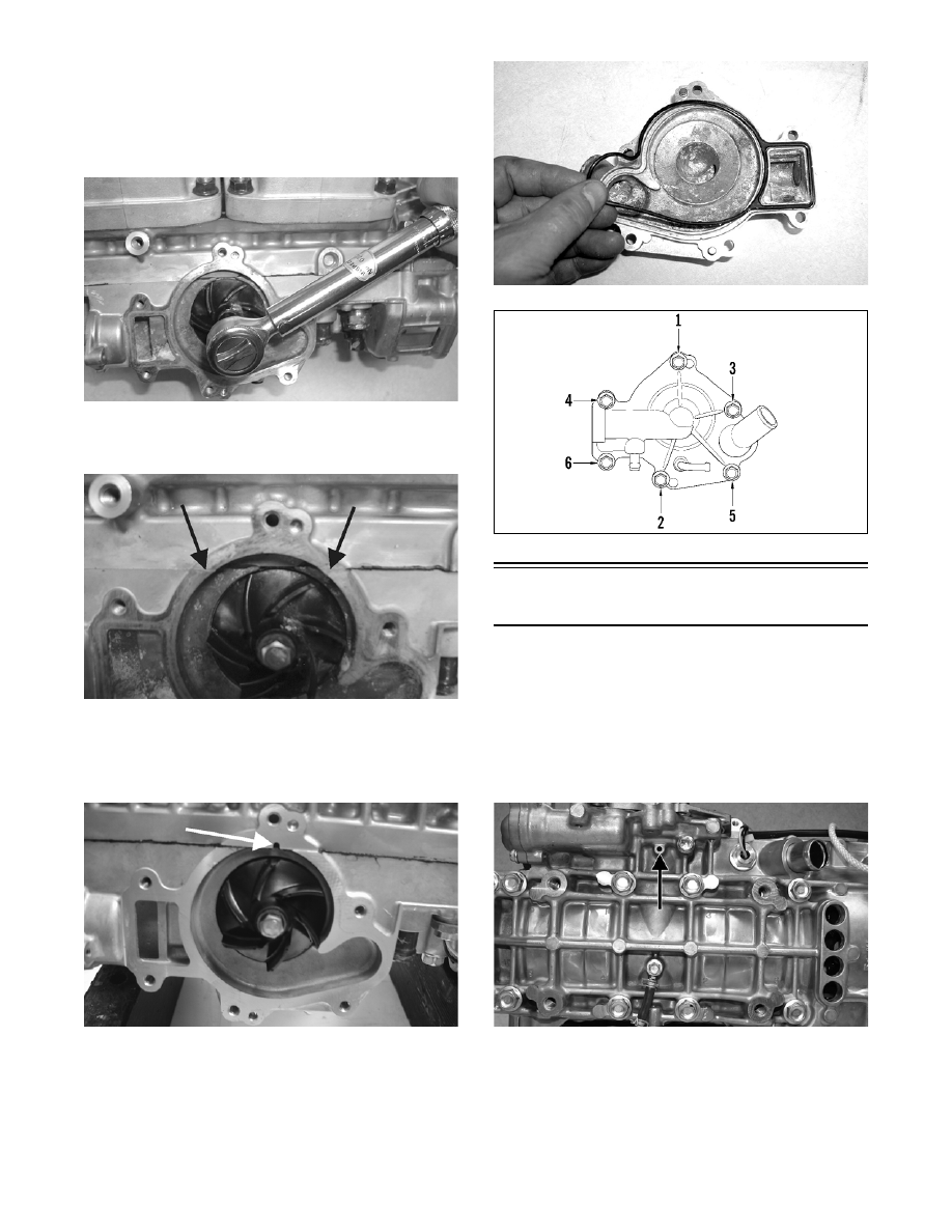
10. Place the impeller into position and secure with a

cap screw and washer. Be sure the rubber side of

the washer is lubricated with a fine coat of oil and

directed towards the impeller. Apply blue Loctite

#243 to the threads of the cap screw and tighten to

6-9 ft-lb.

FC132

11. Apply sealant to the crankcase seam; then install

the alignment pins into the crankcase (if removed).

FC133A

„NOTE: It is important to not get sealant into the
breather hole in the crankcase. If sealant gets into
the hole, carefully remove before proceeding.

FC072B

12. Position the O-ring into the water pump cover;

then install the cover. Install the cap screws; then

using the pattern shown, tighten to 8 ft-lb.

FC134

0742-304

Repairing Water Pump 

(800/1000 cc)

„NOTE: The engine must be removed for this pro-
cedure (see Section 2).

„NOTE: A bleed hole is located in the crankcase
beneath the water pump housing. If there are any
signs of coolant leakage from the bleed hole, the
water pump seals must be replaced. 

FS219A

„NOTE: When servicing the water pump, use
Water Pump Bearing and Seal Tool Kit and Oil Seal
Protector Tool.

3-9

3

1. Loosen the clamps securing the coolant hose to the

water pump and cylinder head; then remove the

hose.

FS222

2. Remove the seven cap screws securing the water

pump cover; then remove the cover and account

for the O-ring seal and two dowel pins.

FS223A

3. Remove the cap screw (A) securing the lower

check valve to the oil pump and account for the

two gaskets; then remove the two cap screws (B)

securing the oil pump to the engine. Remove the

pump.

FS220A

„NOTE: Leave the two upper check valves secured
to the pump.

FS221A

4. Remove the cap screw securing the impeller.

Account for the rubber washer and gasket behind

the cap screw.

FS224

5. Remove the impeller from the shaft.

FS225

„NOTE: If the impeller will not slide off the shaft,
start the cap screw into the shaft and tap on the
cap screw driving the shaft back out of the impel-
ler.

3-10

FC121

6. Remove the oil-injection pump retainer and shaft

from the opposite side of the crankcase. Account

for the thrust washer located between the retainer

and shaft flange.

FS226

7. Using the long seal driver, drive the water pump

mechanical seal from the crankcase.

FS227

8. Using a pair of snap ring pliers, remove the snap

ring securing the oil seal in the crankcase.

FS228

9. Using the hooked end of the long seal driver, pull

the inner seal free of the crankcase.

FS229

ASSEMBLING

1. Thoroughly clean the seal surfaces of the crank-

case.

2. Position the oil seal onto the seal driver (spring

side towards the crankshaft). Gently tap into posi-

tion.

FS230

3. Apply a small amount of grease to the oil seal lips.

4. Using a pair of snap ring pliers, install the snap

ring securing the oil seal in the crankcase.

3-11

3

FS228

5. Using the seal driver, carefully install the outer

water pump mechanical seal. Gently tap the seal

down into position until it seats itself against the

crankcase.

FS232

6. Apply a light coat of grease to the sealing surface

of the oil-injection pump driveshaft; then install

Oil Seal Protector Tool at the end of the shaft.

Twist the shaft as it is pushed through the oil and

water pump seals; then remove the tool. 

FS233

FS234

7. Position the shim on the oil pump end of the shaft;

then with the O-ring installed on the retainer,

install the oil-injection pump retainer.

8. With the O-ring in place on the oil-injection pump,

align the pump with the shaft; then install the

pump. Secure with the cap screws. Tighten the two

cap screws to 5 ft-lb. Place the lower check valve

into position; then secure with the gaskets and cap

screw (A). Tighten securely.

FS220A

„NOTE: When installing the lower check valve,
assure that the gaskets are installed on each side
of the valve.

FS235A

„NOTE: After the oil pump has been secured,
assure that the oil hoses from the pump to the
intake flanges are routed properly.


Content   ..  64  65  66  67   ..