Snowmobile Arctic Cat (2008 year). Manual - part 68
3-16
0742-120
0741-835
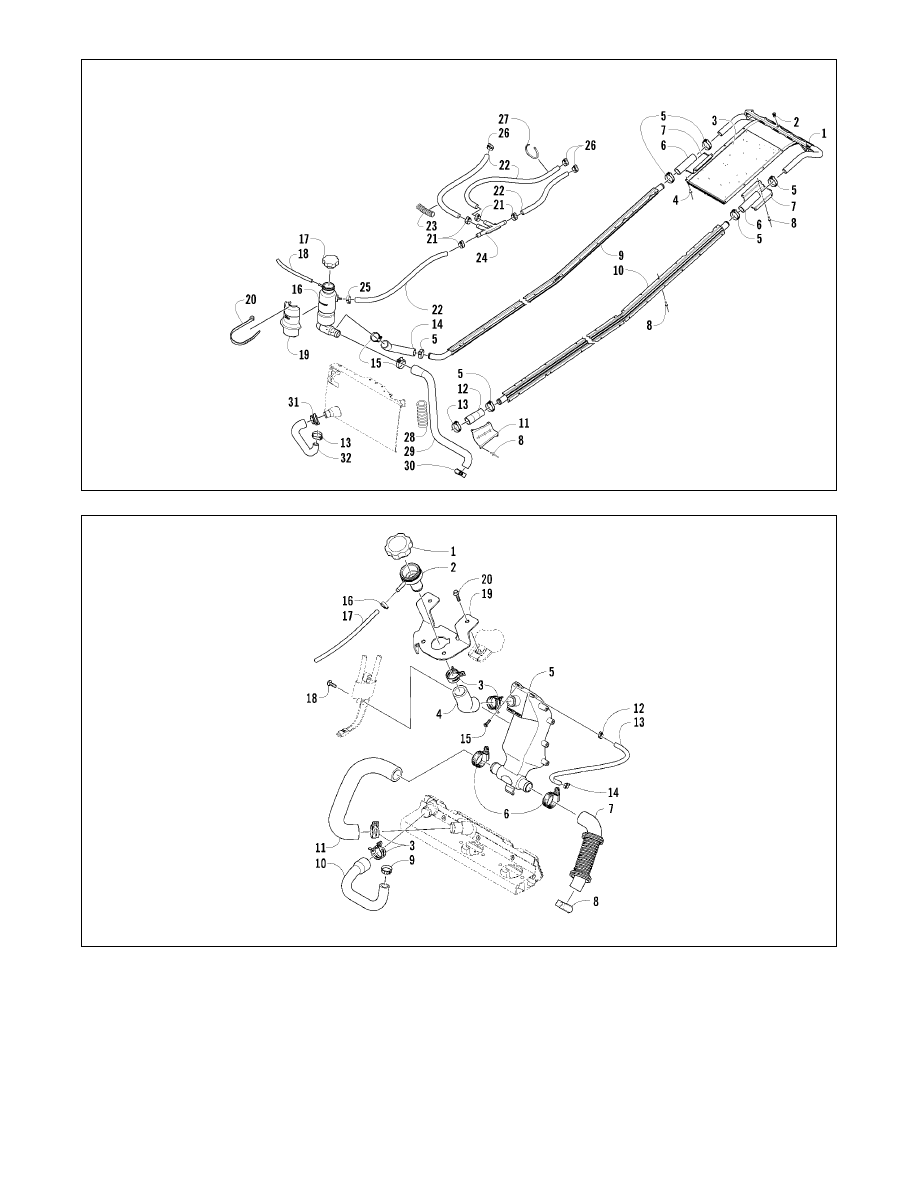
KEY
1. Rear Heat Exchanger
2. Insert
3. Foam
4. Rivet
5. Hose Clamp
6. Hose
7. Hose Protector
8. Rivet
9. Heat Exchanger
10. Heat Exchanger
11. Hose Protector
12. Hose
13. Hose Clamp
14. Hose
15. Hose Clamp
16. Coolant Tank
17. Cap
18. Hose
19. Heat Shield
20. Cable Tie
21. Hose Clamp (1000 cc)
22. Hose
23. Loom (1000 cc)
24. Fitting (1000 cc)
25. Hose Clamp
26. Hose Clamp (1000 cc)
27. Cable Tie (1000 cc)
28. Hose Protector
29. Hose
30. Hose Clamp
31. Hose Clamp
32. Hose
Crossfire/M-Series
KEY
1. Cap
2. Filler Neck
3. Clamp
4. Hose
5. Coolant Tank
6. Clamp
7. Hose
8. Clamp
9. Clamp
10. Hose
11. Hose
12. Clamp
13. Hose
14. Clamp
15. Machine Screw
16. Clamp
17. Hose
18. Self-Tapping Screw
19. Bracket
20. Cap Screw
F-Series 500/600/T500