Snowmobile Polaris High Performance (2001 year). Manual - part 61
CHASSIS/BRAKES/FINAL DRIVE
5.20
Liquid Cooled Brake System
The Type H5LC system, like the Type H4, is a top mounted hydraulic brake system. The difference between the
two systems is the the H5LC is equipped with a brake cooler.
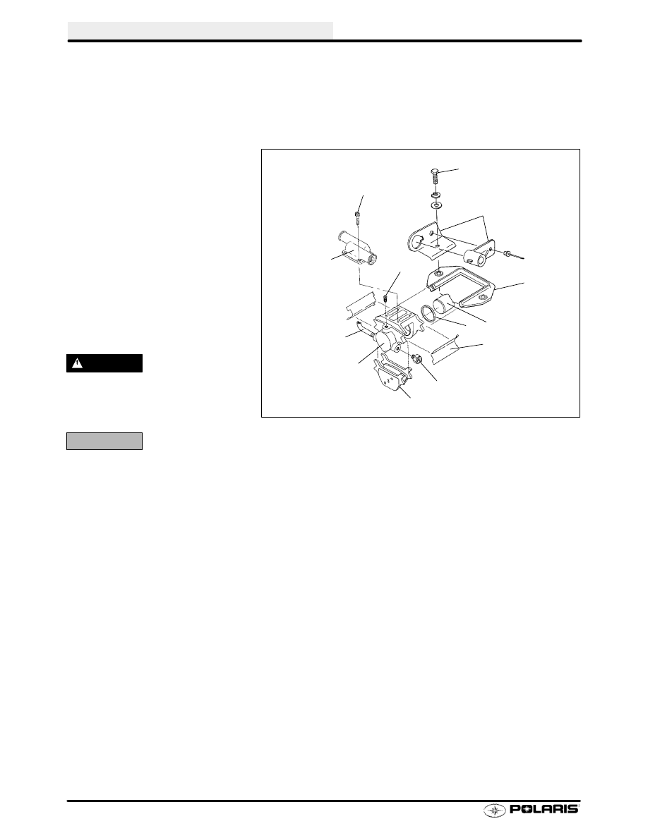
Liquid Cooled Brake Pad Replacement
1.
Carrier Bracket Attaching Bolts
2.
Carrier Bracket
3.
Piston
4.
Piston Seal
5.
Spring Clip
6.
Stop Light Switch
7.
Brake Pads
8.
Brake Line
9.
Bleeder Screw
10. Caliper (Liquid Cooled)
11. Rope Guide
12. Water Cooler Manifold
13. Screws (Cooler Manifold)
WARNING
The rider’s safety depends on cor-
rect installation.
Follow proce-
dures carefully.
CAUTION:
Protect eyes from brake fluid.
1.
Clean any dirt from mount bracket and bolts.
2.
With a 9/16
〉
socket, remove two 3/8 hex bolts and washers from bracket. Remove rope guide. NOTE: Do not
disconnect brake line.
3.
Remove hose clamp from engine side of cooler. Twist and remove hose from cooler, catching and disposing
of antifreeze properly.
4.
Use a drop cloth to protect surfaces from brake fluid spillage. Remove reservoir cover. Using a large
hardwood dowel, or a C clamp vise grip on the center of the old pads, apply pressure toward the caliper piston.
Compress piston back into caliper assembly. Apply pressure slowly to prevent excessive spillage from
master cylinder assembly.
NOTE: Pushing the piston back into the bore will cause the fluid level to rise in the reservoir and possibly overflow.
Remove excess fluid and discard.
5.
Lift bracket and brake assembly off vehicle. Raise open end of cooler and pad assembly to trap antifreeze in
cooler and plug the opening of both cooler and engine hose open end.
1
11
2
3
4
5
6
7
10
8
9
12
13