Volkswagen Golf / Golf GTI / Golf Variant. Manual - part 992


  Index      Volkswagen     Volkswagen Golf / Golf GTI / Golf Variant - service repair manual 2013 year


Search            copyright infringement  


Content   ..  990  991  992  993   ..


Volkswagen Golf / Golf GTI / Golf Variant. Manual - part 992


Removing

Note

The multifunction buttons are attached with the trim molding. The

trim molding and the multifunction buttons are attached to the

steering wheel. The trim can be easily removed with the help of

a second Trim Removal Wedge - 3409- .

– Turn off the ignition and all electrical equipment.
– Remove the ignition key, if equipped.
– Remove the driver side airbag. Refer to ⇒  Body Interior; Rep.

Gr.  69 ; Driver Side Airbag; Overview - Driver Side Airbag .

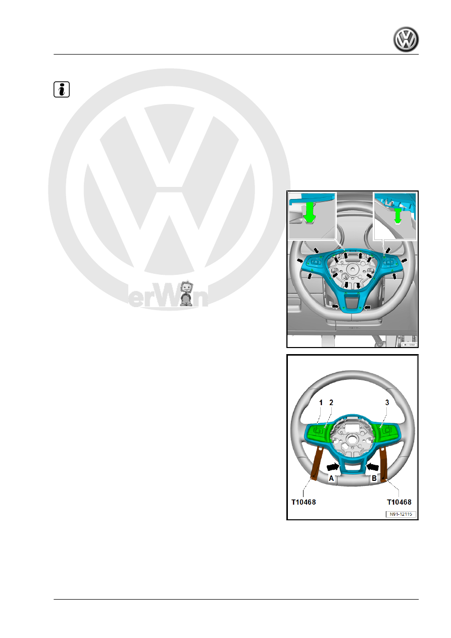
The trim molding is locked in place in the areas near the

-arrows- in the multifunction steering wheel.

– Loosen the trim molding -1- near the -arrows A and B- from

the steering wheel using the Trim Removal Wedge - 3409- .

– Loosen the trim molding -1- near the Left Multifunction Buttons

on Steering Wheel - E440- -2- and Right Multifunction Buttons

on Steering Wheel - E441- -3- using the Lever - Fuel Line -

T10468- .

– Remove the trim molding -1- near the Left Multifunction But‐

tons on Steering Wheel - E440- -2- and Right Multifunction

Buttons on Steering Wheel - E441- -3- using the Door Trim

Pliers - 3392- .

– Remove the trim molding -1- near the -arrows A and B- from

the steering wheel.

– Release and disconnect the connectors.
– Remove the trim molding -1- with the Left Multifunction But‐

tons on Steering Wheel - E440- -2- and Right Multifunction

Buttons on Steering Wheel - E441- -3-.

– Remove the bolts for the Left Multifunction Buttons on Steering

Wheel - E440- -2- and Right Multifunction Buttons on Steering

Wheel - E441- -3- on the back of the trim molding -1-.

– Remove the Left Multifunction Buttons on Steering Wheel -

E440- -2- and Right Multifunction Buttons on Steering Wheel

- E441- -3- from the trim molding -1-.

Installing
Install in reverse order of removal. Note the following:

Note

For a better installation, clip in the trim starting from the bottom.

Tightening Specifications
♦ Refer to

⇒ “8.2 Overview - Multifunction Steering Wheel”, page 55

8.4

Tiptronic Downshift Button on Steering

Wheel - E439- / Tiptronic Upshift Button

on Steering Wheel - E438- , Removing

and Installing

Special tools and workshop equipment required
♦ Torque Wrench 1783 - 2-10Nm - VAG1783-
Removing
The removal and installation is described for the left side. Re‐

moving and installing on the right side is identical.
– Turn off the ignition and all electrical equipment.
– Remove the ignition key, if equipped.
– Remove the Right Multifunction Buttons on Steering Wheel -

E441- / Left Multifunction Buttons on Steering Wheel - E440- .

Refer to

⇒ “8.3 Right/Left Multifunction Buttons On Steering Wheel

E441 / E440 , Removing and Installing”, page 56

 .

– Remove the bolt -1- on the steering wheel.
– Remove the Tiptronic switch -2- with the connecting cable to‐

ward the rear.

Installing
Install in reverse order of removal.
Tightening Specifications
♦ Refer to

⇒ “8.2 Overview - Multifunction Steering Wheel”, page 55

9

Connection for External Multimedia

Devices

⇒ “9.1 Overview - Connection for External Multimedia Devices”,

page 60
⇒ “9.2  External Audio Source Connection R199 , Removing and

Installing”, page 61
⇒ “9.3  USB Distributor R293 , Removing and Installing”,

page 62
⇒ “9.4  USB Charging Socket 1 U37 , Removing and Installing”,

page 62

9.1

Overview - Connection for External Mul‐

timedia Devices

There are several versions of the connection for external multi‐

media devices:
♦ AUX IN - USB, UI4
♦ MEDIA-IN, UF8
♦ USB charging, UI2
Designations are:
♦ External Audio Source Connection - R199- , UI4
♦ External Multimedia Device Interface - R215- , UF8
♦ USB Charging Socket 1 - U37- , UI2
The connection for external multimedia devices is connected to

the Information Electronics Control Module 1 - J794-
Component Location of Connection for External Multimedia De‐

vices
The connection for external multimedia devices -1- is located in

the front center console storage compartment -2-.
Different external audio sources can be connected to the con‐

nection for external multimedia devices:
♦ iPod
♦ MP3 player
♦ USB Stick
The USB Charging Socket 1 - U37- is located in the center con‐

sole storage compartment. It is a component of the Storage

Compartment with Cell Phone Interface - R265- and serves as a

charging connection for the Cellular Telephone - R54- .
Suitable adapter cables are needed. Refer to the Owner's Man‐

ual.
Fault finding is performed via 

Guided Fault Finding

 using the

Vehicle Diagnostic Tester .


Content   ..  990  991  992  993   ..