Volkswagen Golf / Golf GTI / Golf Variant. Manual - part 991


  Index      Volkswagen     Volkswagen Golf / Golf GTI / Golf Variant - service repair manual 2013 year


Search            copyright infringement  


Content   ..  989  990  991  992   ..


Volkswagen Golf / Golf GTI / Golf Variant. Manual - part 991


♦ Rearview camera housing, disconnecting from the pivoting

motor. Refer to 

⇒ page 53

 .

Rearview Camera Housing with Pivoting Motor, Removing from

Pivoting Emblem and Installing
Removing
– Remove the pivoting emblem with the rearview camera and

pivoting motor from the rear lid. Refer to ⇒  Body Exterior; Rep.

Gr.  55 ; Rear Lid; Mechanism, Removing and Installing .

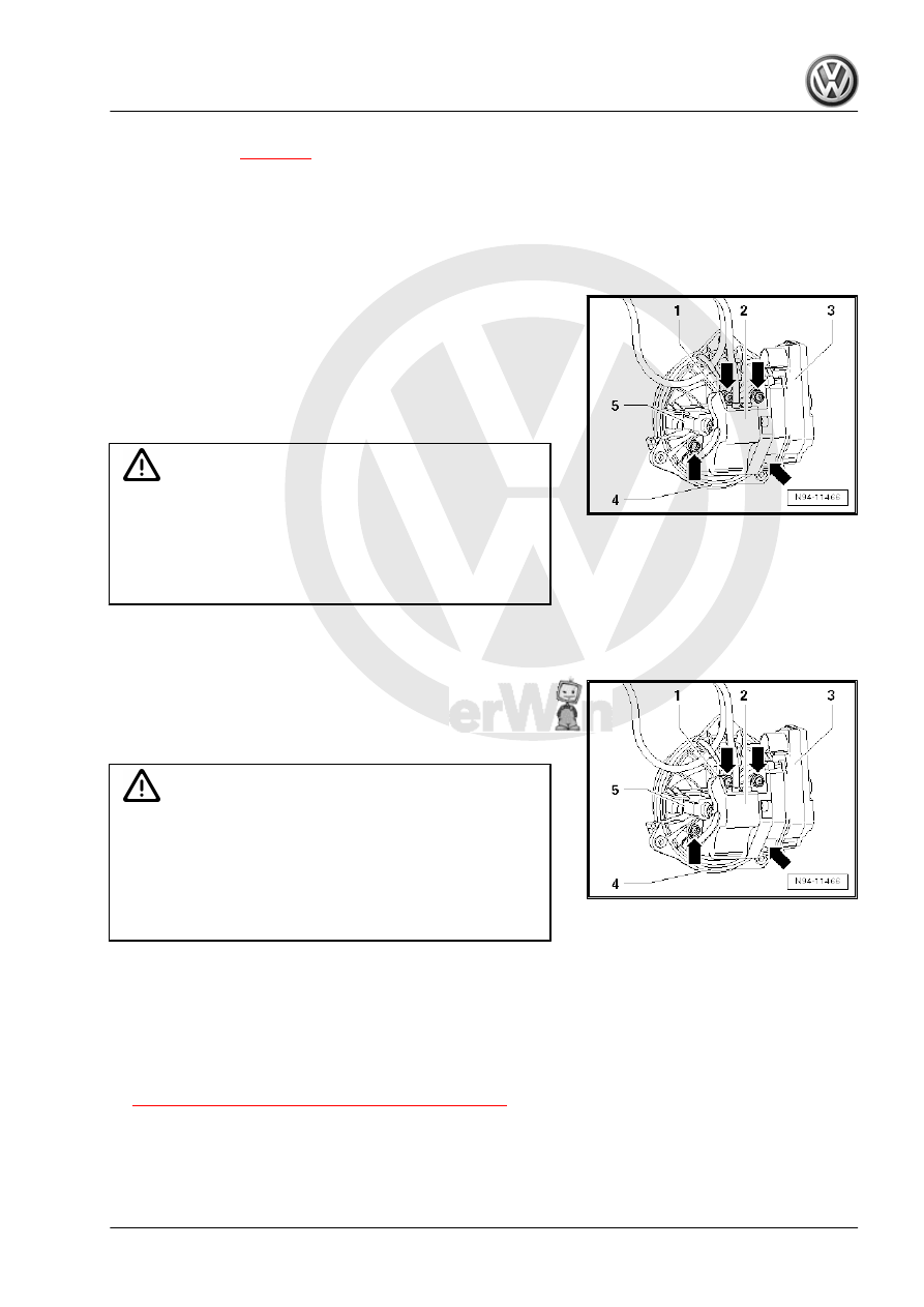
– Release and disconnect the connector -5-.
– Remove bolts -arrows-.
– Remove the rearview camera housing -2- together with the

pivoting motor -3- from the pivoting emblem -4-.

Installing
Install in reverse order of removal. Note the following:

Caution

♦ Risk of leaks
♦ Water could enter the luggage compartment if the seals

are twisted or are not positioned correctly.

♦ Make sure the installed seal is in good condition and in‐

stalled correctly.

– Check the seal between the camera and pivoting emblem and

make sure it is not loose or turned.

– Insert the pivoting motor wire into the wiring guide -1- for the

rearview camera housing -2-.

– Insert the rearview camera housing -2- together with the piv‐

oting motor -3- into the pivoting emblem -4-.

Caution

♦ The pivoting mechanism may be difficult to move.
♦ The bolt in the pivoting motor that is difficult to access

-lower right arrow- may fall out when inserting it in the rear

view camera housing.

♦ The pivoting emblem must be held so that the pivoting

motor -3- is at the bottom when positioning the bolts.

– Install the bolts -arrows-.
– Install the pivoting emblem with the rearview camera and piv‐

oting motor in the rear lid. Refer to ⇒  Body Exterior; Rep. Gr. 

55 ; Rear Lid; Mechanism, Removing and Installing .

Tightening Specifications
♦ Refer to

⇒ “7.3 Overview - Rearview Camera System”, page 52

Rearview Camera Housing, Disconnecting from Pivoting Motor

Special tools and workshop equipment required
♦ Torque Wrench 1783 - 2-10Nm - VAG1783-

Removing
– Rearview camera housing with pivoting motor, removing from

pivoting emblem. Refer to 

⇒ page 53

 .

– Remove the bolts -2-.
– Carefully separate the rearview camera housing from the piv‐

oting motor.

Installing
Install in reverse order of removal. Note the following:
– Check if the release lever and the sliding surface on the piv‐

oting motor are sufficiently lubricated with grease.

– Connect the rearview camera housing and the pivoting motor.
– Install the bolts.
– Install the rear view camera housing with the pivoting motor in

the pivoting emblem. Refer to 

⇒ page 53

 .

Tightening Specifications
♦ Refer to

⇒ “7.3 Overview - Rearview Camera System”, page 52

8

Multifunction Steering Wheel

⇒ “8.1 Overview - Multifunction Steering Wheel”, page 55
⇒ “8.2 Overview - Multifunction Steering Wheel”, page 55
⇒ “8.3 Right/Left Multifunction Buttons On Steering Wheel E441 /

E440 , Removing and Installing”, page 56
⇒ “8.4  Tiptronic Downshift Button on Steering Wheel E439 / Tip‐

tronic Upshift Button on Steering Wheel E438 , Removing and

Installing”, page 58

8.1

Overview - Multifunction Steering Wheel

Buttons are integrated in the steering wheel for easier operation

of the Infotainment system, telephone, navigation, cruise control

system and vehicle menus. On vehicles with Tiptronic, rocker

switches are also installed on the left and right.
The Multifunction Steering Wheel Control Module - J453- ( Left

Multifunction Buttons on Steering Wheel - E440- ) reads out the

button information and transfers it over the LIN Bus to the Steering

Column Electronics Control Module - J527- . From the Steering

Column Electronics Control Module - J527- , the information is

transferred to the individual components via the CAN Bus (com‐

fort) and the Data Bus On Board Diagnostic Interface - J533- .
Fault finding is performed via 

Guided Fault Finding

 using the

Vehicle Diagnostic Tester .

8.2

Overview - Multifunction Steering Wheel

1 - Tiptronic Downshift Button

on Steering Wheel - E439-

❑ Removing and instal‐

ling. Refer to

⇒ “8.4  Tiptronic Down‐

shift Button on Steering

Wheel E439 / Tiptronic

Upshift Button on Steer‐

ing Wheel E438 , Re‐

moving and Installing”,

page 58

 .

2 - 3-Spoke Steering Wheel
3 - Tiptronic Upshift Button on

Steering Wheel - E438-

❑ Removing and instal‐

ling. Refer to

⇒ “8.4  Tiptronic Down‐

shift Button on Steering

Wheel E439 / Tiptronic

Upshift Button on Steer‐

ing Wheel E438 , Re‐

moving and Installing”,

page 58

 .

4 - Screw

❑ 1 Nm
❑ Quantity: 2

5 - Trim Molding
6 - Right Multifunction Buttons

On Steering Wheel - E441-

❑ Removing and instal‐

ling. Refer to

⇒ “8.3 Right/Left Multi‐

function Buttons On

Steering Wheel E441 /

E440 , Removing and

Installing”, page 56

 .

7 - Left Multifunction Buttons On Steering Wheel - E440-

❑ Removing and installing. Refer to

⇒ “8.3 Right/Left Multifunction Buttons On Steering Wheel E441 / E440 , Removing and Installing”, page

56

 .

8 - Screw

❑ 1 Nm
❑ Quantity: 6

8.3

Right/Left Multifunction Buttons On

Steering Wheel -E441- / -E440- , Re‐

moving and Installing

Special tools and workshop equipment required
♦ Trim Removal Wedge - 3409- quantity: 2
♦ Lever - Fuel Line - T10468-
♦ Door Trim Pliers - 3392-
♦ Torque Screwdriver - VAS6494-


Content   ..  989  990  991  992   ..