Volkswagen Golf / Golf GTI / Golf Variant. Manual - part 986


  Index      Volkswagen     Volkswagen Golf / Golf GTI / Golf Variant - service repair manual 2013 year


Search            copyright infringement  


Content   ..  984  985  986  987   ..


Volkswagen Golf / Golf GTI / Golf Variant. Manual - part 986


– Remove the ignition key, if equipped.
The Left Antenna Module - R108- is located on the upper left side

of the rear lid.
– Remove the upper rear lid trim panel. Refer to ⇒  Body Interior;

Rep. Gr.  70 ; Luggage Compartment Trim Panels; Upper Rear

Lid Trim Panel, Removing and Installing .

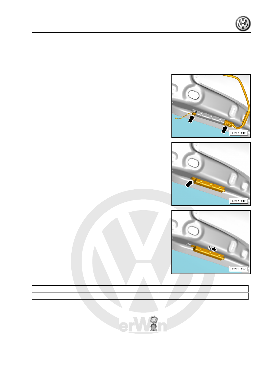
– Release and disconnect the connectors -arrows- from the Left

Antenna Module - R108- .

– Loosen the screw -arrow-.
– Remove the screw with the metal clip and Left Antenna Mod‐

ule - R108- .

– Slide the Left Antenna Module - R108- in the direction of the

-arrow-.

– Remove the Left Antenna Module - R108- .
Installing
Install in reverse order of removal.

Tightening Specifications

Component

Tightening Specification

Screw to Left Antenna Module - R108-

2 Nm

3.4.2

Right Antenna Module - R109- , Remov‐

ing and Installing

Special tools and workshop equipment required
♦ Torque Wrench 1783 - 2-10Nm - VAG1783-

Removing
The Right Antenna Module - R109- is located on the upper right

side of the rear lid.
– Turn off the ignition and all electrical equipment.
– Remove the ignition key, if equipped.
– Remove the rear lid upper trim panel. Refer to ⇒  Body Interior;

Rep. Gr.  70 ; Luggage Compartment Trim Panels; Upper Rear

Lid Trim Panel, Removing and Installing .

– Release and disconnect the connectors -arrows- from the

Right Antenna Module - R109- .

– Loosen the screw -arrow-.
– Remove the screw with the metal clip and Right Antenna Mod‐

ule - R109- .

– Slide the Right Antenna Module - R109- in the direction of the

-arrow-.

– Remove the Right Antenna Module - R109- .
Installing
Install in reverse order of removal.

Tightening Specifications

Component

Tightening Specification

Screw to Right Antenna Module - R109-

2 Nm

3.5

Roof Antenna, Removing and Installing

⇒ “3.5.1 Roof Antenna, Removing and Installing, Sedan”,

page 35
⇒ “3.5.2 Roof Antenna, Removing and Installing, Wagon”,

page 35

3.5.1

Roof Antenna, Removing and Installing,

Sedan

Special tools and workshop equipment required
♦ Torque Wrench 1783 - 2-10Nm - VAG1783-
The back of the headliner must be lowered in order to remove the

Roof Antenna - RX5- .
The antenna wires are connected directly to the base of the Roof

Antenna - RX5- .
Removing
– Turn off the ignition and all electrical equipment.
– Remove the ignition key, if equipped.
– Loosen the B-pillar upper trim panel. Refer to ⇒  Body Interior;

Rep. Gr.  70 ; Passenger Compartment Trim Panel; B-Pillar

Trim Panel, Removing and Installing .

– Remove the roof end strip. Refer to ⇒  Body Interior; Rep. Gr. 

70 ; Roof Trim Panels; Roof End Strip, Removing and Instal‐

ling .

– Remove the C-pillar trim panel. Refer to ⇒  Body Interior; Rep.

Gr.  70 ; Passenger Compartment Trim Panel; C-Pillar Trim

Panel, Removing and Installing .

– Lower the back of the headliner.
– Release and disconnect the connectors -1- from the antenna

wires.

– Remove the bolt -3- with the clip.
– Remove the Roof Antenna - RX5- -2-.
Installing
Install in reverse order of removal. Note the following:
– Position the Roof Antenna - RX5- and press it down until it

latches.

Tightening Specifications

Component

Tightening Specification

Bolt -3- to Roof Antenna - RX5-

6 Nm

3.5.2

Roof Antenna, Removing and Installing,

Wagon

Special tools and workshop equipment required
♦ Torque Wrench 1783 - 2-10Nm - VAG1783-
The back of the headliner must be lowered in order to remove the

Roof Antenna - RX5- .

The antenna wires are connected directly to the base of the Roof

Antenna - RX5- .
Removing
– Turn off the ignition and all electrical equipment.
– Then remove the ignition key, if equipped.
– Remove the C-pillar trim panel. Refer to ⇒  Body Interior; Rep.

Gr.  70 ; Passenger Compartment Trim Panel; C-Pillar Trim

Panel, Removing and Installing .

– Remove the roof end strip. Refer to ⇒  Body Interior; Rep. Gr. 

70 ; Roof Trim Panels; Roof End Strip, Removing and Instal‐

ling .

– Remove the D-pillar trim panel. Refer to ⇒  Body Interior; Rep.

Gr.  70 ; Passenger Compartment Trim Panel; D-Pillar Trim

Panel, Removing and Installing .

– If installed, remove the screen separator mounting eye bolts,

but do not remove the mounting eyes. Refer to ⇒  Body Interior;

Rep. Gr.  68 ; Equipment; Screen Separator Bracket, Remov‐

ing and Installing .

– Lower the back of the headliner.
– Release and disconnect the connectors -1- from the antenna

wires.

– Remove the bolt -3- with the clip.
– Remove the Roof Antenna - RX5- -2- from the outside.
Installing
Install in reverse order of removal. Note the following:
– Position the Roof Antenna - RX5- and press it down until it

latches.

Tightening Specifications

Component

Tightening Specification

Bolt -3- to Roof Antenna - RX5-

6 Nm

3.6

Vehicle GPS Antennas, Removing and

Installing

⇒ “3.6.1  Vehicle GPS Antenna 1 R259 Removing and Installing,

GPS”, page 36
⇒ “3.6.2  Vehicle GPS Antenna 2 R260 , Removing and Installing,

GSM”, page 37

3.6.1

Vehicle GPS Antenna 1 - R259- Remov‐

ing and Installing, GPS

The Vehicle GPS Antenna 1 - R259- is located behind the left rear

bumper cover.
Removing
– Turn off the ignition and all electrical equipment.
– Remove the ignition key, if equipped.
– Remove the rear bumper cover. Refer to ⇒  Body Exterior;

Rep. Gr.  63 ; Rear Bumper; Bumper Cover, Removing and

Installing .


Content   ..  984  985  986  987   ..