Volkswagen Golf / Golf GTI / Golf Variant. Manual - part 984


  Index      Volkswagen     Volkswagen Golf / Golf GTI / Golf Variant - service repair manual 2013 year


Search            copyright infringement  


Content   ..  982  983  984  985   ..


Volkswagen Golf / Golf GTI / Golf Variant. Manual - part 984


2.6.2

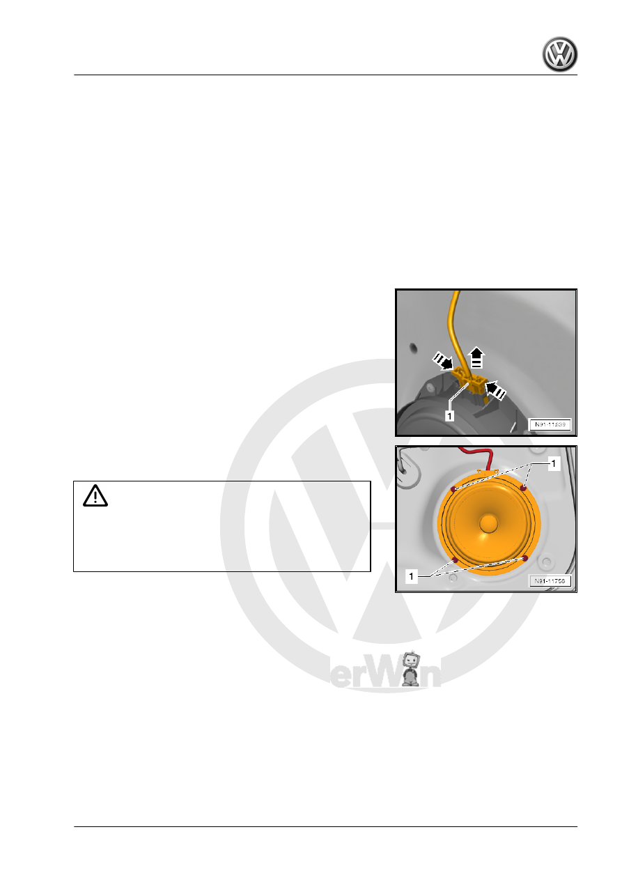
Left/Right Rear Bass Speaker -R15- / -

R17- , 4-Door Vehicles, Removing and

Installing

The Left Rear Bass Speaker - R15- / Right Rear Bass Speaker -

R17- are located at the bottom of the rear doors.
The removal and installation is described for the left side. Re‐

moving and installing on the right side is identical.
Removing
– Turn off the ignition and all electrical equipment.
– Remove the ignition key, if equipped.
– Remove the rear door trim panel. Refer to ⇒  Body Interior;

Rep. Gr.  70 ; Rear Door Trim Panels; Rear Door Trim Panel,

Removing and Installing .

– Release and disconnect the connector -1- from the bass

speaker in the direction of the -arrow-.

– Drill out the rivets -1- using a suitable drill.
– Remove the bass speaker.

Caution

Always remove any shavings resulting from the drilling, other‐

wise they may cause corrosion damage later.
If the paint on the door frame gets damaged during drilling,

touch-up immediately.

Installing
Install in reverse order of removal. Note the following:
– Secure the speaker using special blind rivets when installing

(Note the part number. Refer to the Parts Catalog).

2.7

Left/Right Front Bass Speaker -R21- / -

R23- , Removing and Installing

The Left Front Bass Speaker - R21- / Right Front Bass Speaker

- R23- are located at the bottom of the front doors.
The removal and installation is described for the left side. Re‐

moving and installing on the right side is identical.
Removing
– Turn off the ignition and all electrical equipment.
– Remove the ignition key, if equipped.

– Remove the front door trim panel. Refer to ⇒  Body Interior;

Rep. Gr.  70 ; Front Door Trim Panels; Front Door Trim Panel,

Removing and Installing .

– Release and disconnect the connector -1- from the bass

speaker in direction of -arrow-.

– Drill out the rivets -1- using a suitable drill.
– Remove the bass speaker.

Caution

Always remove any shavings resulting from the drilling, other‐

wise they may cause corrosion damage later.
If the paint on the door frame gets damaged during drilling,

touch-up immediately.

Installing
Install in reverse order of removal. Note the following:
– Secure the speaker using special blind rivets when installing

(Note the part number. Refer to the Parts Catalog).

2.8

Subwoofer - R211- , Removing and In‐

stalling

⇒ “2.8.1  Subwoofer R211 , Removing and Installing, Sedan”,

page 26
⇒ “2.8.2  Subwoofer R211 , Removing and Installing, Wagon”,

page 27

2.8.1

Subwoofer - R211- , Removing and In‐

stalling, Sedan

The Subwoofer - R211- is located in the spare wheel well.
Removing
– Turn off the ignition and all electrical equipment.
– Remove the ignition key, if equipped.
– Remove the luggage compartment floor.

– Release and disconnect the connector -2- from the Subwoofer

- R211- -1-.

– Remove the bolt -3- on the Subwoofer - R211- -1-.
– Remove the Subwoofer - R211- -1- upward.
Installing
Install in reverse order of removal.

Tightening Specifications

Component

Tightening Specification

Bolt -3- to the Subwoofer - R211-

9 Nm

2.8.2

Subwoofer - R211- , Removing and In‐

stalling, Wagon

The Subwoofer - R211- is located in the spare wheel well.
Removing
– Turn off the ignition and all electrical equipment.
– Remove the ignition key, if equipped.
– Fold up the luggage compartment floor.
– Release and disconnect the connector -3- from the Subwoofer

- R211- -1-.

– Remove the bolt -2- on the Subwoofer - R211- -1-.
– Remove the Subwoofer - R211- -1- upward.
Installing
Install in reverse order of removal.

Tightening Specifications

Component

Tightening Specification

Bolt -2- to Subwoofer - R211-

9 Nm

3

Antenna Systems

⇒ “3.1 Component Location Overview - Antenna Systems”, page

28
⇒ “3.2  AM Frequency Filter R177 , Removing and Installing”,

page 31
⇒ “3.3  FM Frequency Filter in the Negative Wire R178 / FM Fre‐

quency Filter in the Positive Wire R179 , Removing and Installing”,

page 32
⇒ “3.4 Antenna Module, Removing and Installing”, page 32
⇒ “3.5 Roof Antenna, Removing and Installing”, page 35

3.1

Component Location Overview - Anten‐

na Systems

⇒ “3.1.1 Component Location Overview - Antenna Systems, Se‐

dan”, page 28
⇒ “3.1.2 Component Location Overview - Antenna Systems,

Wagon”, page 30

3.1.1

Component Location Overview - Antenna Systems, Sedan

1 - FM Frequency Filter in Pos‐

itive Wire - R179-

❑ On the left window

frame of the rear lid

❑ FM plus trap circuit
❑ Its function is to prevent

antenna signals from

shorting to ground

❑ Removing and instal‐

ling. Refer to

⇒ “3.3  FM Frequency

Filter in the Negative

Wire R178 / FM Fre‐

quency Filter in the Pos‐

itive Wire R179 , Re‐

moving and Installing”,

page 32

 .

2 - AM Frequency Filter -

R177-

❑ On the lower right of the

rear lid

❑ Its function is to prevent

antenna signals from

shorting to ground

❑ Removing and instal‐

ling. Refer to

⇒ “3.2  AM Frequency

Filter R177 , Removing

and Installing”,

page 31

 .

3 - FM Frequency Filter in Neg‐

ative Wire - R178-

❑ On the right window

frame of the rear lid

❑ FM minus trap circuit


Content   ..  982  983  984  985   ..