Volkswagen Golf / Golf GTI / Golf Variant. Manual - part 983


  Index      Volkswagen     Volkswagen Golf / Golf GTI / Golf Variant - service repair manual 2013 year


Search            copyright infringement  


Content   ..  981  982  983  984   ..


Volkswagen Golf / Golf GTI / Golf Variant. Manual - part 983


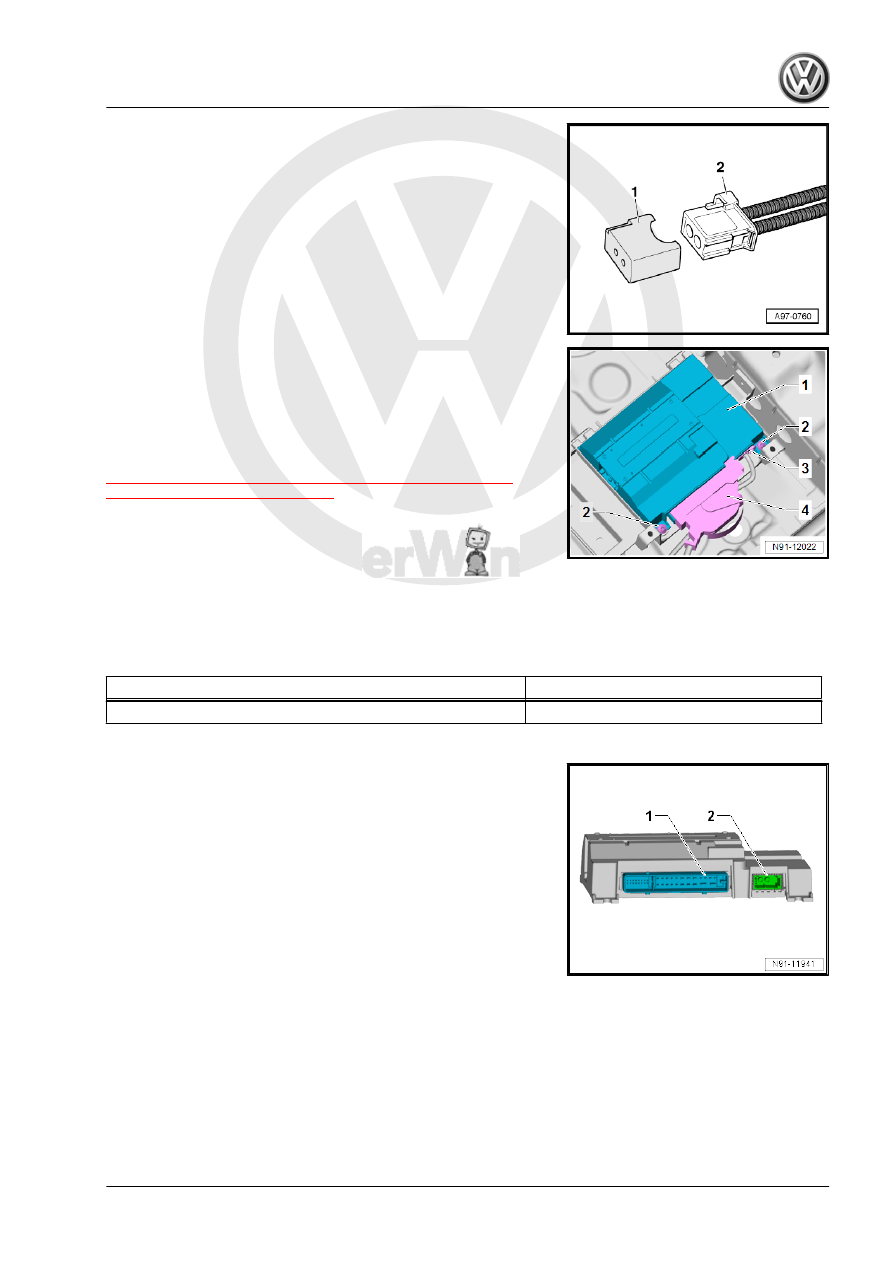
– Insert the Fiber-Optic Repair Set - Connector Protective Caps

- VAS6223/9- -1- onto the MOST Bus connector -2-.

– Release and disconnect the connector -4- from the Digital

Sound System Control Module - J525- -1-.

– Remove the screws -2-.
– Pivot the Digital Sound System Control Module - J525- -1- out

of the bracket.

Remove the bracket. Refer to

⇒ “2.3.2  Digital Sound System Control Module J525 Bracket,

Removing and Installing”, page 21

 .

Installing
Install in reverse order of removal. Note the following:
When installing, make sure that the Digital Sound System Control

Module - J525- is properly inserted into the notch on the bracket.
Make sure the cover is mounted correctly on the front edge of the

bracket when installing it.

Tightening Specifications

Component

Tightening Specification

Screws -2- to bracket

3 Nm

Connectors to Digital Sound System Control Module - J525-
1 - 38-Pin Connector - T38-
2 - MOST Bus
Refer to ⇒ Wiring diagrams, Troubleshooting & Component loca‐

tions

2.3.2

Digital Sound System Control Module -

J525- Bracket, Removing and Installing

Special tools and workshop equipment required
♦ Torque Wrench 1783 - 2-10Nm - VAG1783-
Removing
– Remove the Digital Sound System Control Module - J525- .

Refer to

⇒ “2.3.1  Digital Sound System Control Module J525 , Re‐

moving and Installing”, page 20

 .

– Fold back the carpet and floor insulation at the center tunnel

and floor panel.

– Remove the bolt -1- on the center tunnel and the nuts -2- on

the bracket.

– Remove the bracket for the Digital Sound System Control

Module - J525- -3-.

Installing
Install in reverse order of removal.

Tightening Specifications

Component

Tightening Specification

Bolt -1-

6 Nm

Nuts -2-

6 Nm

2.4

Left/Right Rear Treble Speaker -R14- /

-R16- , Removing and Installing

⇒ “2.4.1 Left/Right Rear Treble Speaker R14 / R16 , 2-Door Ve‐

hicles, Removing and Installing”, page 22
⇒ “2.4.2 Left/Right Rear Treble Speaker R14 / R16 , 4-Door Ve‐

hicles, Removing and Installing”, page 23

2.4.1

Left/Right Rear Treble Speaker -R14- /

-R16- , 2-Door Vehicles, Removing and

Installing

The Left Rear Treble Speaker - R14- / Right Rear Treble Speaker

- R16- are located in the rear side trim panels.
The removal and installation is described for the left side. Re‐

moving and installing on the right side is identical.
If the treble speaker must be replaced, then the speaker mesh

must also be replaced.
Removing
– Turn off the ignition and all electrical equipment.
– Remove the ignition key, if equipped.
– Remove the side trim panel. Refer to ⇒  Body Interior; Rep.

Gr.  70 ; Passenger Compartment Trim; Side Trim Panel, Re‐

moving and Installing .

– Disengage the connector and disconnect.
– Detach the treble speaker with the speaker mesh from the side

trim panel using workshop tools.

Installing
Install in reverse order of removal. Note the following:
– Insert the treble speaker with the speaker mesh into the door

trim panel.

– Heat the pins using workshop tools so that the speaker mesh

rests securely and flush in the side trim panel.

2.4.2

Left/Right Rear Treble Speaker -R14- /

-R16- , 4-Door Vehicles, Removing and

Installing

The Left Rear Treble Speaker - R14- / Right Rear Treble Speaker

- R16- are located in the rear door trim panels.
The removal and installation is described for the left side. Re‐

moving and installing on the right side is identical.
If the treble speaker must be replaced, then the speaker mesh

must also be replaced.
Removing
– Turn off the ignition and all electrical equipment.
– Remove the ignition key, if equipped.
– Remove the rear door trim panel. Refer to ⇒  Body Interior;

Rep. Gr.  70 ; Rear Door Trim Panels; Rear Door Trim Panel,

Removing and Installing .

– Disengage the connector and disconnect.
– Detach the treble speaker with the speaker mesh from the

door trim panel using workshop tools.

Installing
Install in reverse order of removal. Note the following:
– Insert the treble speaker with the speaker mesh into the door

trim panel.

– Heat the pins using workshop tools so that the speaker mesh

rests securely and flush in the side trim panel.

2.5

Left/Right Front Treble Speaker -R20- /

-R22- , Removing and Installing

The Left Front Treble Speaker - R20- / Right Front Treble Speaker

- R22- are located in the A-pillar trim panels.
The removal and installation is described for the left side. Re‐

moving and installing on the right side is identical.
If the treble speaker must be replaced, then the A-pillar trim panel

must also be replaced.
Removing
– Turn off the ignition and all electrical equipment.
– Remove the ignition key, if equipped.
– Remove the A-pillar trim panel. Refer to ⇒  Body Interior; Rep.

Gr.  70 ; Passenger Compartment Trim; A-Pillar Trim Panel,

Removing and Installing .

Installing
Install in reverse order of removal.

2.6

Left/Right Rear Bass Speaker -R15- / -

R17- , Removing and Installing

⇒ “2.6.1 Left/Right Rear Bass Speaker R15 / R17 , 2-Door Vehi‐

cles, Removing and Installing”, page 24
⇒ “2.6.2 Left/Right Rear Bass Speaker R15 / R17 , 4-Door Vehi‐

cles, Removing and Installing”, page 25

2.6.1

Left/Right Rear Bass Speaker -R15- / -

R17- , 2-Door Vehicles, Removing and

Installing

The Left Rear Bass Speaker - R15- / Right Rear Bass Speaker -

R17- are located in the sidewall.
The removal and installation is described for the left side. Re‐

moving and installing on the right side is identical.
Removing
– Turn off the ignition and all electrical equipment.
– Remove the ignition key, if equipped.
– Remove the side trim panel. Refer to ⇒  Body Interior; Rep.

Gr.  70 ; Passenger Compartment Trim; Sill Panel Strip, Re‐

moving and Installing .

– Release and disconnect the connector -1- from the bass

speaker in direction of -arrow-.

– Drill out the rivets -1- using a suitable drill.
– Remove the bass speaker.

Caution

Always remove any shavings from the sidewall resulting from

the drilling, otherwise they may cause corrosion damage later.
If the paint on the door frame gets damaged during drilling,

touch-up immediately.

Installing
Install in reverse order of removal. Note the following:
– Secure the speaker using special blind rivets when installing

(Note the part number. Refer to the Parts Catalog).


Content   ..  981  982  983  984   ..