Volkswagen Golf / Golf GTI / Golf Variant. Manual - part 960


  Index      Volkswagen     Volkswagen Golf / Golf GTI / Golf Variant - service repair manual 2013 year


Search            copyright infringement  


Content   ..  958  959  960  961   ..


Volkswagen Golf / Golf GTI / Golf Variant. Manual - part 960


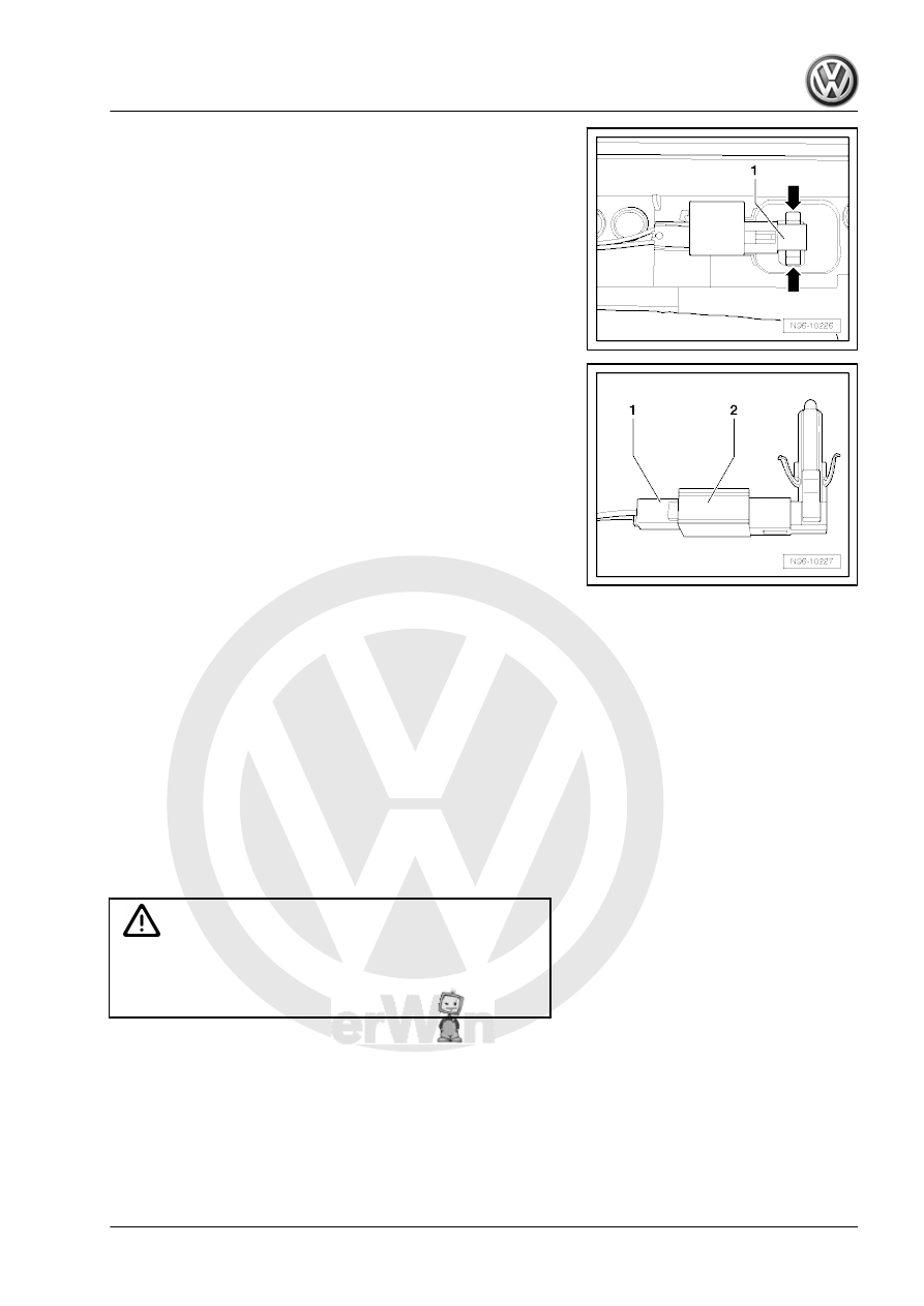
– Press the tabs -arrows- and remove the Central Locking -Safe-

Indicator Lamp - K133- -1- from the door trim panel.

– Release and disconnect the connector -1- from the Central

Locking -Safe- Indicator Lamp - K133- -2-.

Installing
Install in reverse order of removal.
– Perform a function test.

1.12

Left/Right Front Entry Lamp -W31- / -

W32- , Removing and Installing

Special tools and workshop equipment required
♦ Trim Removal Wedge - 3409-
Removal and installation for all entry lamps is performed in the

same way and is only described for one lamp.
♦ Left Front Entry Lamp - W31-
♦ Right Front Entry Lamp - W32-
♦ Left Rear Entry Lamp - W33-
♦ Right Rear Entry Lamp - W34-
Check the entry lamps using the output diagnostic test mode on

each door control module.

Caution

Risk of damaging the component surfaces.

♦ When positioning a prying tool, put commercially available

adhesive tape over the component in the visible area.

Removing
– Turn off the ignition and all electrical equipment.
– Remove the ignition key, if equipped.
– Pry out the lamp carefully using -3409- or a screwdriver.

– Disconnect the connector and remove the lamp.
Installing
Install in reverse order of removal.

1.13

Entry Lamp Bulb, Removing and Instal‐

ling

Removing
– Remove the front entry lamp. Refer to

⇒ “1.12 Left/Right Front Entry Lamp W31 / W32 , Removing

and Installing”, page 245

 .

– Pry the diffusion lens carefully out of the housing in direction

of -arrow-.

– Remove the bulb -1- straight out of the socket.
Installing
Install in reverse order of removal.

1.14

Driver/Front Passenger Door Warning

Lamp -W30- / -W36- , Removing and In‐

stalling

The door warning lamp and the entry lamp make up one compo‐

nent. The can be remove and installed together.
– Entry Lamp, Removing and installing. Refer to

⇒ “1.12 Left/Right Front Entry Lamp W31 / W32 , Removing

and Installing”, page 245

 .

1.15

Driver/Front Passenger Door Opener Il‐

lumination Bulb -L108- / -L109- , Re‐

moving and Installing

The removal and installation is described for the left side. Re‐

moving and installing on the right side is identical.

Caution

There is a risk of damaging the fiber-optic cable.

♦ Only touch the fiber-optic cable on the light fittings in the

area of the interior door mechanism.

Removing
– Turn off the ignition and all electrical equipment.
– Remove the ignition key, if equipped.
– Remove the front door trim panel. Refer to ⇒  Body Interior;

Rep. Gr.  70 ; Front Door Trim Panels; Front Door Trim Panel,

Removing and Installing .

Finger Position on the Fiber-Optic Cable
1 - Fiber-optic cable
A - Index and middle fingers
B - Thumb
– Disengage the connector and disconnect.
– Disengage the fiber-optic cable on the front bracket -1- in the

direction of the arrow -A-.

– Carefully lift the fiber-optic cable -3- in the direction of the ar‐

row -B- and pivot from the interior door mechanism -4-.

– Remove the fiber-optic cable from the mount -2-.
Installing
Install in reverse order of removal.
– Perform a function test.

1.16

Left/Right Front Door Ambient Lighting

Bulb 2 - L203- / -L204- , Removing and

Installing

The Left Front Door Ambient Lighting Bulb 2 - L203- and the Right

Front Door Ambient Lighting Bulb 2 - L204- are integrated in the

door trim panel decorative strip and cannot be replaced individu‐

ally.
– Remove the front door trim panel decorative strip. Refer to ⇒ 

Body Interior; Rep. Gr.  70 ; Front Door Trim Panels; Overview

- Front Door Trim Panel .

1.17

Left/Right Rear Entry Lamp -W33- / -

W34- , Removing and Installing

Removal and installation for all entry lamps is performed in the

same way and is only described for one lamp.

– Entry Lamp, Removing and installing. Refer to

⇒ “1.12 Left/Right Front Entry Lamp W31 / W32 , Removing

and Installing”, page 245

 .

1.18

Left/Right Rear Door Warning Lamp -

W37- / -W38- , Removing and Installing

The door warning lamp and the entry lamp make up one compo‐

nent. The can be remove and installed together.
– Entry Lamp, Removing and installing. Refer to

⇒ “1.12 Left/Right Front Entry Lamp W31 / W32 , Removing

and Installing”, page 245

 .

1.19

Selector Lever Transmission Range Po‐

sition Display Unit - Y26- , Removing

and Installing

The Selector Lever Transmission Range Position Display Unit -

Y26- -1- is integrated in the selector lever boot and cannot be

replaced individually.
Removing
– Turn off the ignition and all electrical equipment.
– Remove the ignition key, if equipped.
– Remove the selector lever boot. Refer to ⇒  Rep. Gr.  34 ;

Selector Mechanism; Selector Lever Handle, Removing and

Installing .

Installing
Install in reverse order of removal.
– Perform a function test.

1.20

Luggage Compartment Lamp - W3- ,

Removing and Installing

⇒ “1.20.1  Luggage Compartment Lamp W3 , Removing and In‐

stalling, Sedan”, page 248
⇒ “1.20.2  Luggage Compartment Lamp W3 , Removing and In‐

stalling, Wagon”, page 249

1.20.1

Luggage Compartment Lamp - W3- ,

Removing and Installing, Sedan

Caution

Risk of damaging the component surfaces.

♦ When positioning a prying tool, put commercially available

adhesive tape over the component in the visible area.

Removing
– Turn off the ignition and all electrical equipment.
– Remove the ignition key, if equipped.


Content   ..  958  959  960  961   ..