Volkswagen Golf / Golf GTI / Golf Variant. Manual - part 892
 

  Index      Volkswagen     Volkswagen Golf / Golf GTI / Golf Variant - service repair manual 2013 year


Search            copyright infringement  


Content   ..  890  891  892  893   ..


Volkswagen Golf / Golf GTI / Golf Variant. Manual - part 892


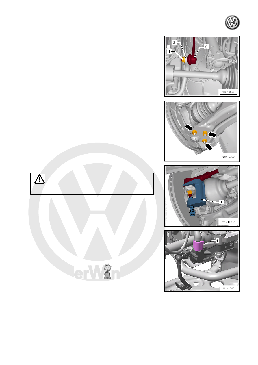
– Remove the hex nut -1- from the right and left coupling rod

-3-.

– Remove the coupling rod -3- from the stabilizer bar -2- on the

left and right sides.

– Remove the nuts -arrows- on the left and right side of the ve‐

hicle.

– Remove the control arm from the ball joint.

– Loosen the nut from the tie rod end, but do not unscrew yet.

Caution

To protect the thread, screw the nut on the pin a few turns.

– Remove the tie rod end from the wheel bearing housing and

remove the nut.

1 - -T10187-

Vehicles with Level Control System Sensor
– Disconnect the connector -1- from the Left Front Level Control

System Sensor - G78- or  Right Front Level Control Sensor -

G289- .

Continuation for all Vehicles

– Disconnect the connector -1- for the Oil Level Thermal Sensor

- G266- .

– If equipped, disconnect the connector -2- from the After-Run

Coolant Pump - V51- . To do so, open the catch -3- in the

direction of the -arrow- and release the connector.

– Remove the clips -1- and -2- for the wiring harness -3- from

the subframe and the steering gear.

– Remove the steering gear bolts -1-.

– Place the -VAS6931- -1- under the subframe.
– Secure the subframe and lower it approximately 10 cm.

– Remove the bolts -arrows- and remove the heat shield -1- from

the steering gear.

Note

Different heat shields -1- are installed depending on the engine.

On some engine versions, the connectors for the steering gear

are accessible without having to remove the heat shield.

– Disconnect the connectors -1 and 2- from the steering gear.

– Unclip the wiring harness -1- from the steering gear -2-

-arrows-.

– Remove the expanding clip -arrow-.
– Lower the subframe using the -VAS6931- .
– Pry the steering gear off of the subframe, for example, using

a large screwdriver and remove it toward the rear.

– Set the steering gear down as illustrated.
Avoid damage to the control module -1-.
Installing
Install in reverse order of removal. Note the following:
The steering gear threaded sleeves must be seated in the sub‐

frame holes.

– Connect the connectors -1 and 2- so that they audibly click into

place.

Note

Coat the seal on the steering gear with lubricant such as soft

soap before installing the steering gear.

After attaching steering gear to drive axle, make sure that seal

on steering gear is positioned on the mounting plate without

and kinks and is sealed correctly. The opening to the foot well

must sealed correctly. Ingress of water and/or noises may be

the result.

Make sure sealing surfaces are clean.

– Position the steering gear on the subframe.
– Attach the bolts for the steering gear and the stabilizer bar.


Content   ..  890  891  892  893   ..