Volkswagen Golf / Golf GTI / Golf Variant. Manual - part 890


  Index      Volkswagen     Volkswagen Golf / Golf GTI / Golf Variant - service repair manual 2013 year


Search            copyright infringement  


Content   ..  888  889  890  891   ..


Volkswagen Golf / Golf GTI / Golf Variant. Manual - part 890


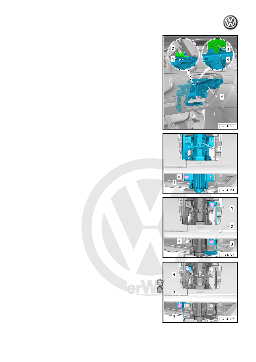
– Engage the steering column -1- in the assembly aids on the

mounting bracket at the bottom -2- and at the top -3-.

– Align the steering column -2- to the mounting bracket. Install

the bolt -1- hand-tight.

– Install the right bracket for the knee airbag -3-.
– Install the bolts -1 and 2- hand-tight.

– Install the left bracket for the knee airbag -3-.
– Install the bolts -1 and 2- hand-tight.

– Tighten the bolts -1, 2, 3, and 4- one after the other to the

tightening specification.

– The flat side of the steering column -1- must be positioned on

the flat side of the steering gear -2-. At the same time, the

opening on the steering gear must align precisely with the hole

for the bolt -arrows-.

– Install the universal joint -2- on the steering pinion in the op‐

posite direction of the -arrow-.

– Install and tighten the new hex bolt -1-.

– Fold the footwell trim panel -2- forward and secure it with the

bolt -1-.

Vehicles with Ignition Switch
– Connect the connector -arrow- with the Anti-Theft Immobilizer

Reader Coil - D2- .

– Connect the connector -2-.

Vehicle with “Keyless Access” Keyless Locking and Starting Sys‐

tem
– Connect the connector -1-.
– Clip the wire into the retainer on the Electronic Steering Col‐

umn Lock Control Module - J764- -arrow-.

Continuation for All Vehicles
– Install the steering column switch module. Refer to ⇒  Electri‐

cal Equipment; Rep. Gr.  94 ; Steering Column Switch Module;

Steering Column Switch Module, Removing and Installing .

– Insert the lower wiring bracket -2- so that the tabs engage in

the guide on the steering column.

– Insert the wiring guide -1-. The tabs -arrows- must engage on

the steering column.

– Install the footwell vent under the steering column. Refer to ⇒ 

Heating, Ventilation and Air Conditioning; Rep. Gr.  87 ; Air

Routing; Overview - Air Routing and Air Distribution in Pas‐

senger Compartment .

– Install the knee airbag. Refer to ⇒  Body Interior; Rep. Gr.  69 ;

Knee Airbags; Overview - Knee Airbag .

– Install the lower steering column trim panel. Refer to ⇒  Body

Interior; Rep. Gr.  68 ; Storage Compartments and Covers;

Lower Steering Column Trim Panel, Removing and Installing .

– Install the upper steering column trim panel. Refer to ⇒  Body

Interior; Rep. Gr.  68 ; Storage Compartments and Covers;

Upper Steering Column Trim Panel, Removing and Installing .

– Install the steering wheel. Refer to

⇒ “1.2 Steering Wheel, Removing and Installing”, page 336

 .

– Install the driver side airbag unit. Refer to ⇒  Body Interior; Rep.

Gr.  69 ; Driver Side Airbag; Overview - Driver Side Airbag .

– Perform a basic setting on the Steering Angle Sensor - G85-

using the ⇒ Vehicle diagnostic tester.

Tightening Specifications
♦ Refer to 

⇒ “2.1 Overview - Steering Column”, page 338

♦ Refer to ⇒  Heating, Ventilation and Air Conditioning; Rep. Gr. 

87 ; Air Routing; Overview - Air Routing and Air Distribution in

Passenger Compartment .

♦ Refer to ⇒  Electrical Equipment; Rep. Gr.  94 ; Steering Col‐

umn Switch Module; Steering Column Switch Module, Re‐

moving and Installing .

♦ Refer to ⇒  Body Interior; Rep. Gr.  69 ; Knee Airbags; Over‐

view - Knee Airbag

♦ Refer to ⇒  Body Interior; Rep. Gr.  69 ; Driver Side Airbag;

Overview - Driver Side Airbag .

♦ Refer to ⇒  Body Interior; Rep. Gr.  68 ; Storage Compartments

and Covers; Lower Steering Column Trim Panel, Removing

and Installing .

♦ Refer to ⇒  Body Interior; Rep. Gr.  68 ; Storage Compartments

and Covers; Upper Steering Column Trim Panel, Removing

and Installing .

2.5

Electronic Steering Column Lock Con‐

trol Module - J764- , Removing and In‐

stalling

Special tools and workshop equipment required
♦ 7/16 Inch Extractor - T10424US-
♦ Vehicle Diagnostic Tester

Caution

This procedure contains mandatory replaceable parts. Refer

to component overview prior to starting procedure.


Content   ..  888  889  890  891   ..