Volkswagen Golf / Golf GTI / Golf Variant. Manual - part 893
 

  Index      Volkswagen     Volkswagen Golf / Golf GTI / Golf Variant - service repair manual 2013 year


Search            copyright infringement  


Content   ..  891  892  893  894   ..


Volkswagen Golf / Golf GTI / Golf Variant. Manual - part 893


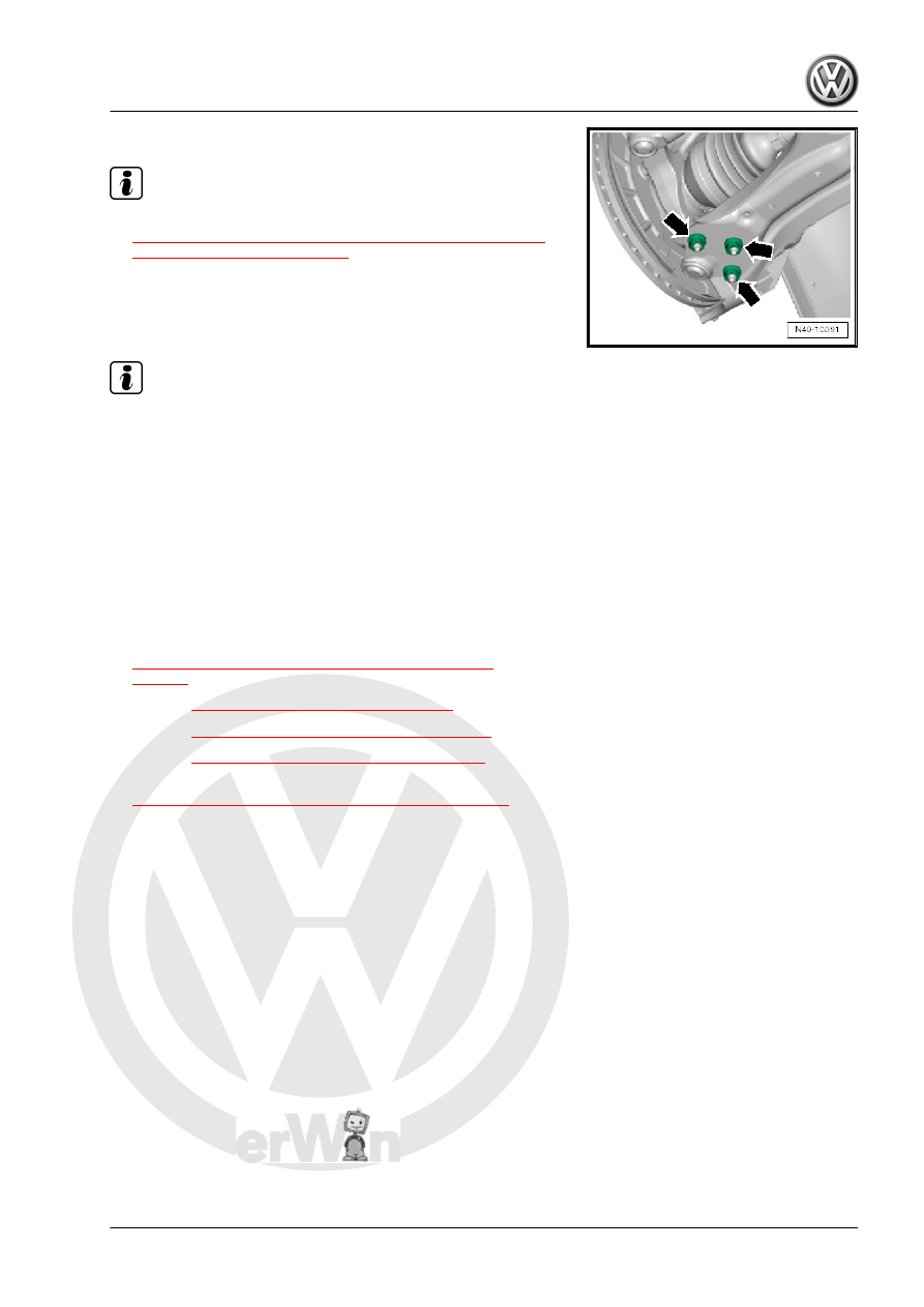
– Tighten nuts -arrows-.

Note

♦

Tighten the nuts -arrows- in curb weight position. Refer to

⇒ “3.8.1 Wheel Bearing in Curb Weight, Lifting Vehicles with

Coil Spring, Front Axle”, page 6

 .

♦

Make sure the ball joint boot is not damaged or twisted.

– Install the lower noise insulation. Refer to ⇒  Body Exterior;

Rep. Gr.  66 ; Noise Insulation; Overview - Noise Insulation .

Note

Make sure the ball joint boot is not damaged or twisted.

– Bolt the universal joint to the steering gear.
– Connect the battery. Refer to ⇒  Electrical Equipment; Rep.

Gr.  27 ; Battery; Battery, Disconnecting and Connecting .

– Perform the Steering Angle Sensor - G85- basic setting using

the ⇒ Vehicle diagnostic tester.

It is necessary to adapt the electro-mechanical power steering

using the Vehicle Diagnostic Tester ⇒ Vehicle diagnostic tester if

new steering gear was installed.
Tightening Specifications
♦ Refer to

⇒ “4.1 Overview - Lower Control Arm and Ball Joint”,

page 54

♦ Refer to 

⇒ “2.1 Overview - Subframe”, page 16

♦ Refer to 

⇒ “3.1 Overview - Steering Gear”, page 350

♦ Refer to 

⇒ “3.6 Steering Gear, Servicing”, page 363

♦ Refer to

⇒ “1.1 Wheel Bolt Tightening Specifications”, page 286

♦ Bolts for pendulum support. Refer to ⇒  Rep. Gr.  10 ; Subframe

Mount; Overview - Subframe Mount .

♦ Exhaust system to subframe. Refer to ⇒  Rep. Gr.  26 ; Exhaust

Pipes/Mufflers; Overview - Muffler .

♦ Noise insulation bolts. Refer to ⇒  Body Exterior; Rep. Gr.  66 ;

Noise Insulation; Overview - Noise Insulation .

If the steering wheel is still crooked after using the -T10486/1-

then an axle alignment is necessary. In this case the record it in

the vehicles axle alignment log.

3.3

Boot, Removing and Installing

Special tools and workshop equipment required
♦ Hose Clip Pliers - VAG1275A-
♦ Torque Wrench 1332 40-200Nm - VAG1332-
♦ Open Ring Wrench - 24mm - VAG1332/11-
♦ Locking Pliers - VAS6199-
♦ Vehicle Diagnostic Tester

Caution

This procedure contains mandatory replaceable parts. Refer

to component overview prior to starting procedure.

Mandatory Replacement Parts
♦ Clamps - CV Boot
Removing

Note

♦

If the boot is faulty, moisture and dirt will penetrate into steering

gear. There must be a noticeable grease film present on steer‐

ing rack in area of splines. If grease film is not present, steering

gear must be replaced.

♦

Replace the steering gear:

♦

If there is corrosion.

♦

If it is damaged.

♦

If it is worn out.

♦

If there is dirt on the steering rack.

– Turn steering wheel into straight ahead position.
– Loosen the wheel bolts.
– Raise the vehicle.
– Remove the wheel.
– Mark the location of the nut on the tie rod.
– Remove the tie rod end. Refer to

⇒ “3.5 Tie Rod End, Removing and Installing”, page 362

 .

– Clean outside of steering gear in area of boot.
While doing this, no dirt must enter the steering gear through the

faulty boot.
– Open the clamps.
– Remove the boot from the steering gear and the tie rod.

Note

♦

If corrosion, damage, wear-out or first signs of soiling on steer‐

ing rack can be seen, complete steering gear must be re‐

placed.

♦

If no grease film is visible on steering rack, steering gear must

also be replaced completely.

Installing

Caution

Do not lubricate the steering rack.

– Turn steering wheel into straight ahead position.

– Guide new clamp and boot onto tie rod.
– Lightly grease the sealing surface of the boot to the tie rod with

grease from the repair kit.

– Slide the boot -2- onto the tie rod -1- as illustrated.
– Secure spring clamp on boot using Hose Clip Pliers -

VAG1275A- .

– Lightly grease the sealing surface of the boot to the steering

gear housing with grease from the repair kit.

– Push the boot all the way onto the steering gear housing.

– Tighten the new clamp using the Locking Pliers - VAS6199- to

the extent depicted in the illustration.

– Install the tie rod end up to the marking made earlier during

the removal. Refer to

⇒ “3.5 Tie Rod End, Removing and Installing”, page 362

 .

– Install the front wheel and tighten the bolts.
– Perform vehicle alignment.
– If both tie rods were replaced, then the basic setting for the

Steering Angle Sensor - G85- must be performed using the

Vehicle Diagnostic Tester .

– Then perform the basic setting to the steering using the Vehi‐

cle Diagnostic Tester .

Tightening Specifications
♦ Refer to 

⇒ “3.1 Overview - Steering Gear”, page 350

♦ Refer to 

⇒ “3.6 Steering Gear, Servicing”, page 363

♦ Refer to

⇒ “1.1 Wheel Bolt Tightening Specifications”, page 286

3.4

Tie Rod, Removing and Installing

Special tools and workshop equipment required
♦ Torque Wrench 1332 40-200Nm - VAG1332-
♦ Torque Wrench Insert - Open Jaw - VAG1923-
♦ Puller - Ball Joint - T10187-
♦ Locking Pliers - VAS6199-

Caution

This procedure contains mandatory replaceable parts. Refer

to component overview prior to starting procedure.

Mandatory Replacement Parts
♦ Clamps - Tie Rod
Removing
– Turn steering wheel into straight ahead position.

– Loosen the wheel bolts.
– Raise the vehicle.
– Remove the wheel.
– Clean outside of steering gear in area of boot.
– Loosen nut of tie rod ball joint, but do not unscrew yet.

Caution

To protect thread, screw nut on pin a few turns.

– Remove the tie rod end from the wheel bearing housing and

remove the nut.

1 - Puller - Ball Joint - T10187-
– Open the clamps and push back boot.
– Turn the steering as follows:

For the left tie rod, turn the steering to the left until stop
For the right tie rod, turn the steering to the right until stop

– Remove tie rod.
1 - Torque Wrench Insert - Open Jaw - VAG1923-
2 - Torque Wrench 1332 40-200Nm - VAG1332-

Note

♦

If corrosion, damage, wear-out or first signs of soiling on steer‐

ing rack can be seen, complete steering gear must be re‐

placed.

♦

If no grease film is visible on steering rack, steering gear must

also be replaced completely.

Installing
Installation is the reverse of removal, with special attention to the

following:

Caution

Do not lubricate the steering rack.


Content   ..  891  892  893  894   ..