Volkswagen Golf / Golf GTI / Golf Variant. Manual - part 872


  Index      Volkswagen     Volkswagen Golf / Golf GTI / Golf Variant - service repair manual 2013 year


Search            copyright infringement  


Content   ..  870  871  872  873   ..


Volkswagen Golf / Golf GTI / Golf Variant. Manual - part 872


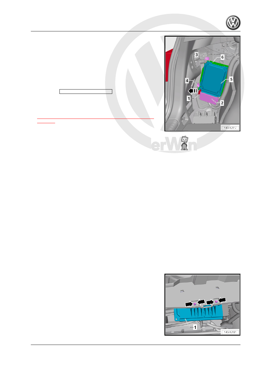
– Release the release lever -1- in direction of -arrow-.
– Remove the connector -2-.
– Push the tabs -3 and 4- to the rear.
– Slide the Electronic Damping Control Module - J250- -5- down‐

ward from the bracket -6-.

Installing
Install in reverse order of removal while noting the following:
– If the Electronic Damping Control Module - J250- was re‐

placed, the 

Replace control module

 function must be per‐

formed using the Vehicle Diagnostic Tester .

– If the control position was reprogrammed and if the vehicle has

lane assist, then it will then be necessary to calibrate the driver

assistance systems front camera. Refer to

⇒ “6.1 Driver Assistance Systems Front Camera, Calibrating”,

page 327

 .

1.2.2

Electronic Damping Control Module -

J250- , Removing and Installing, Golf

Wagon

Special tools and workshop equipment required
♦ Vehicle Diagnostic Tester
Removing
Component location: the Electronic Damping Control Module -

J250- is installed in the luggage compartment behind the left side

trim panel.
– Disconnect the battery. Refer to ⇒  Electrical Equipment; Rep.

Gr.  27 ; Battery; Battery, Disconnecting and Connecting .

– Remove the ignition key.
Vehicles with “Keyless Access” Keyless Locking and Starting

System
– Switch the ignition off and open the driver door so the steering

wheel lock engages.

Continuation for All Vehicles
– Remove the left luggage compartment side trim panel. Refer

to ⇒  Body Interior; Rep. Gr.  70 ; Luggage Compartment Trim

Panels; Luggage Compartment Side Trim Panel, Removing

and Installing .

– Remove the tool bag.
– Release the tabs -arrows-.
– Remove the bracket -1-.

– Remove the control module -1- from the bracket -2-.

– Remove the release -1- in direction of -arrow-.
– Remove the connector -2-.
Installing
Install in reverse order of removal and note the following:

– Push the control module -1- as far as possible in the bracket

-2- until the tab -arrow- engages in the bracket.

– If the Electronic Damping Control Module - J250- was re‐

placed, the 

Replace control module

 function must be per‐

formed using the Vehicle Diagnostic Tester .

– If the control position was reprogrammed and if the vehicle has

lane assist, then it will then be necessary to calibrate the driver

assistance systems front camera. Refer to

⇒ “6.1 Driver Assistance Systems Front Camera, Calibrating”,

page 327

 .

1.3

Left/Right Front Body Acceleration Sen‐

sor -G341- / -G342- , Removing and

Installing

Special tools and workshop equipment required
♦ Torque Wrench - VAG1410-

Removing
– Remove the seal from the entire length of the plenum chamber

cover.

– Remove the clips.
– Lift the plenum chamber cover -1- to maximum 60 mm.
a - 60 mm

– Release and disconnect the connector -1-.
– Remove the bolt -2-.
– Remove the Front Body Acceleration Sensor .
Installing
Installation is the reverse of removal, with special attention to the

following:

– Insert the Front Body Acceleration Sensor -1- so that the con‐

nector connection -arrow- faces opposite the direction of trav‐

el.

– Secure the Front Body Acceleration Sensor -1- with the bolt

-2-.

Installation position: angle tolerance -a- is ±10°. The installation

position of the Front Body Acceleration Sensor may deviate

around this angle from the vehicle longitudinal axis.
– Perform the basic setting for the wheel damping electronics.

Refer to Vehicle Diagnostic Tester .

Tightening Specifications

Component

Tightening Specification

Front Body Acceleration Sen‐

sor to body

8 Nm

1.4

Left Rear Body Acceleration Sensor -

G699- , Removing and Installing

Special tools and workshop equipment required
♦ Torque Wrench - VAG1410-
♦ Vehicle Diagnostic Tester
Removing
– Remove the left luggage compartment side trim panel. Refer

to ⇒  Body Interior; Rep. Gr.  70 ; Luggage Compartment Trim

Panels; Luggage Compartment Side Trim Panel, Removing

and Installing .

– Release and disconnect the connector -1-.
– Remove the bolt -2- and then remove the Rear Body Acceler‐

ation Sensor - G343- -3-.

Installing
Installation is the reverse of removal, with special attention to the

following:

– Insert the Rear Body Acceleration Sensor - G343- -1- so that

the tab -arrow A- engages in the hole -arrow B-.

– Perform the basic setting for the wheel damping electronics.

Refer to Vehicle Diagnostic Tester .

Tightening Specifications

Component

Tightening Specification

Rear Body Acceleration Sensor

- G343- to body

8 Nm


Content   ..  870  871  872  873   ..